HealthRider Rc270 Bike English Manual - Page 6
Be careful not to pinch the wire har
 |
View all HealthRider Rc270 Bike manuals
Add to My Manuals
Save this manual to your list of manuals |
Page 6 highlights
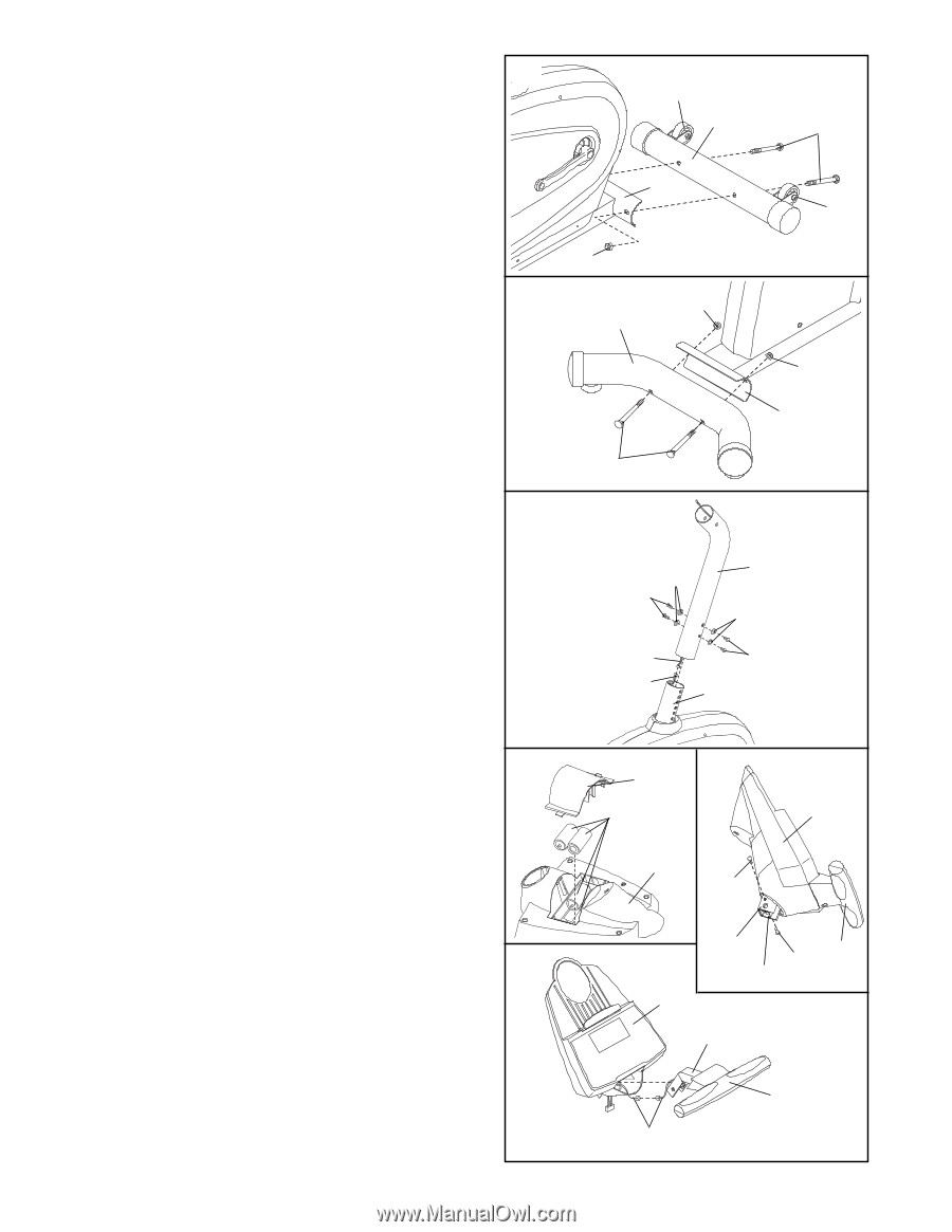
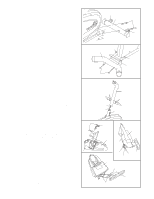
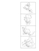
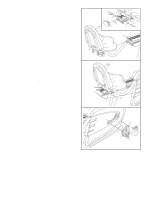
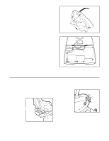
1. Attach the Front Stabilizer (2) to the front of the 1 Frame (1) with two M10 x 75mm Carriage Bolts (72) and two M10 Nylon Locknuts (45). Make sure that the Front Stabilizer is turned so the Wheels (75) are not touching the floor. 2. Attach the Rear Stabilizer (3) to the rear of the 2 Frame (1) with two M10 x 82mm Carriage Bolts (63) and two M10 Nylon Locknuts (45). 3. While a second person holds the Upright (6) near 3 the Frame (1) as shown, connect the Upper Wire Harness (16) to the Lower Wire Harness (77). Carefully slide the Upright (6) onto the Frame (1); be careful to avoid pinching the Wire Harnesses (16, 77). Slide the Upright to the desired height and then attach it with four M8 x 25mm Button Screws (27) and four M8 Split Washers (70). Note: The height of the Upright can be adjusted later if desired. 75 2 1 45 45 3 63 72 75 45 1 6 70 27 70 16 27 77 1 4. The Console (9) requires four "D" batteries (not 4 included); alkaline batteries are recommended. Remove the battery cover from the back of the Console. Press four batteries into the Console as shown. Make sure that the negative (-) ends of the batteries are facing the springs. Reattach the battery cover. Refer to inset drawing A. Connect the wire harness on the Handgrip Pulse Sensor (71) to the indicated wire harness on the Console (9). Insert both wire harnesses into the opening in the bottom of the A Console. Next, insert the metal tube on the Handgrip Pulse Sensor into the opening in the bottom of the Console. Be careful not to pinch the wire har- nesses. Refer to inset drawing B. Align the holes in the bracket on the Console (9) with the holes in the metal tube on the Handgrip Pulse Sensor (71). Tighten two M4 x 12mm Screws (60) through the bracket into the tube as shown. 6 Battery B Cover Batteries 9 9 60 Bracket 71 60 Tube 9 Tube 71 Wire Harnesses
-
 1
1 -
 2
2 -
 3
3 -
 4
4 -
 5
5 -
 6
6 -
 7
7 -
 8
8 -
 9
9 -
 10
10 -
 11
11 -
 12
12 -
13
-
14
-
15
-
16
-
17
-
18
-
19
-
20
-
21
-
22
-
23
-
24
 |
 |