HP 15-bn000 15-ay099 250 G5 Notebook PC 256 G5 Notebook PC - Maintenance and S - Page 66
Optical drive board, Remove the Phillips PM2.0×2.4 screw
 |
View all HP 15-bn000 manuals
Add to My Manuals
Save this manual to your list of manuals |
Page 66 highlights
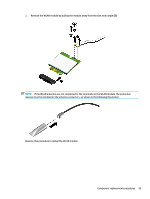
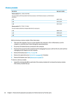
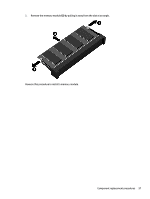
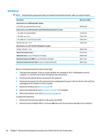
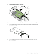
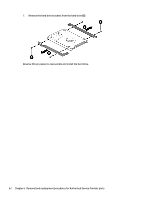
Optical drive board Description Optical drive board (includes cable) Spare part number 855007-001 Before removing the optical drive board, follow these steps: 1. Shut down the computer. If you are unsure whether the computer is off or in Hibernation, turn the computer on, and then shut it down through the operating system. 2. Disconnect all external devices connected to the computer. 3. Disconnect the power from the computer by first unplugging the power cord from the AC outlet and then unplugging the AC adapter from the computer. 4. Remove the battery (see Battery on page 48). 5. Remove the optical drive (see Optical drive on page 49), if installed. 6. Remove the bottom cover (see Bottom cover on page 52). To remove the optical drive board: 1. Disconnect the cable from the system board (1). 2. Remove the Phillips PM2.0×2.4 screw (2) that secures the optical drive board to the computer. 3. Rotate the connector side of the board upward, and then pull the board and cable up and out of the computer (3). Reverse this procedure to install the optical drive board and cable. 58 Chapter 6 Removal and replacement procedures for Authorized Service Provider parts
-
 1
1 -
2
-
3
-
4
-
5
-
6
-
7
-
8
-
9
-
10
-
11
-
12
-
13
-
14
-
15
-
16
-
17
-
18
-
19
-
20
-
21
-
22
-
23
-
24
-
25
-
26
-
27
-
28
-
29
-
30
-
31
-
32
-
33
-
34
-
35
-
36
-
37
-
38
-
39
-
40
-
41
-
42
-
43
-
44
-
45
-
46
-
47
-
48
-
49
-
50
-
51
-
52
-
53
-
54
-
55
-
56
-
57
-
58
-
59
-
60
-
 61
61 -
 62
62 -
 63
63 -
 64
64 -
 65
65 -
 66
66 -
 67
67 -
 68
68 -
 69
69 -
 70
70 -
 71
71 -
72
-
73
-
74
-
75
-
76
-
77
-
78
-
79
-
80
-
81
-
82
-
83
-
84
-
85
-
86
-
87
-
88
-
89
-
90
-
91
-
92
-
93
-
94
-
95
-
96
-
97
-
98
-
99
-
100
-
101
-
102
-
103
-
104
-
105
-
106
-
107
-
108
-
109
-
110
-
111
-
112
-
113
-
114
-
115
-
116
-
117
-
118
-
119
-
120
-
121
-
122
-
123
-
124
-
125
-
126
-
127
-
128
-
129
-
130
-
131
-
132
-
133
-
134
-
135
-
136
-
137
-
138
 |
 |