HP 15-bn000 15-ay099 250 G5 Notebook PC 256 G5 Notebook PC - Maintenance and S - Page 88
the back of the panel., Rotate the display panel onto the keyboard
 |
View all HP 15-bn000 manuals
Add to My Manuals
Save this manual to your list of manuals |
Page 88 highlights
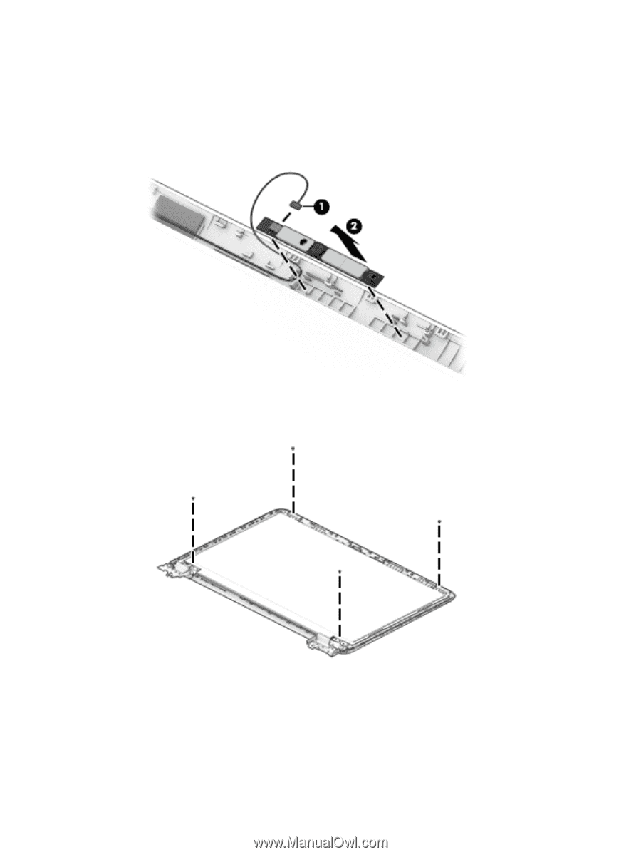
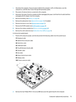
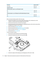
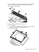
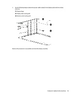
2. To remove the webcam/microphone module: a. Position the display assembly with the top edge toward you. b. Disconnect the cable (1) from the module. c. Remove the webcam/microphone module (2). (The module is attached to the display enclosure with double-sided tape.) 3. To remove the display panel: a. Remove the four Phillips PM2.0×3.0 screws that secure the display panel to the enclosure. b. Rotate the display panel onto the keyboard (1) to gain access to the display cable connection on the back of the panel. c. On the back of the display panel, release the adhesive strip (2) that secures the display panel cable to the display panel, and then disconnect the cable (3). 80 Chapter 6 Removal and replacement procedures for Authorized Service Provider parts
-
 1
1 -
2
-
3
-
4
-
5
-
6
-
7
-
8
-
9
-
10
-
11
-
12
-
13
-
14
-
15
-
16
-
17
-
18
-
19
-
20
-
21
-
22
-
23
-
24
-
25
-
26
-
27
-
28
-
29
-
30
-
31
-
32
-
33
-
34
-
35
-
36
-
37
-
38
-
39
-
40
-
41
-
42
-
43
-
44
-
45
-
46
-
47
-
48
-
49
-
50
-
51
-
52
-
53
-
54
-
55
-
56
-
57
-
58
-
59
-
60
-
61
-
62
-
63
-
64
-
65
-
66
-
67
-
68
-
69
-
70
-
71
-
72
-
73
-
74
-
75
-
76
-
77
-
78
-
79
-
80
-
81
-
82
-
 83
83 -
 84
84 -
 85
85 -
 86
86 -
 87
87 -
 88
88 -
 89
89 -
 90
90 -
 91
91 -
 92
92 -
 93
93 -
94
-
95
-
96
-
97
-
98
-
99
-
100
-
101
-
102
-
103
-
104
-
105
-
106
-
107
-
108
-
109
-
110
-
111
-
112
-
113
-
114
-
115
-
116
-
117
-
118
-
119
-
120
-
121
-
122
-
123
-
124
-
125
-
126
-
127
-
128
-
129
-
130
-
131
-
132
-
133
-
134
-
135
-
136
-
137
-
138
 |
 |