HP 15-r029wm HP 15 Notebook PC Compaq 15 Notebook PC HP 250 G3 Notebook PC HP - Page 67
and the touchpad button board cable
 |
View all HP 15-r029wm manuals
Add to My Manuals
Save this manual to your list of manuals |
Page 67 highlights
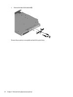
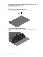
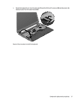
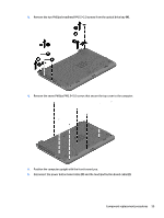
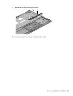
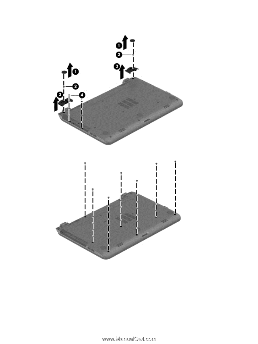
3. Remove the two Phillips broadhead PM2.5×2.0 screws from the optical drive bay (4). 4. Remove the seven Phillips PM2.5×5.0 screws that secure the top cover to the computer. 5. Position the computer upright with the front toward you. 6. Disconnect the power button board cable (1) and the touchpad button board cable (2). Component replacement procedures 59
-
 1
1 -
2
-
3
-
4
-
5
-
6
-
7
-
8
-
9
-
10
-
11
-
12
-
13
-
14
-
15
-
16
-
17
-
18
-
19
-
20
-
21
-
22
-
23
-
24
-
25
-
26
-
27
-
28
-
29
-
30
-
31
-
32
-
33
-
34
-
35
-
36
-
37
-
38
-
39
-
40
-
41
-
42
-
43
-
44
-
45
-
46
-
47
-
48
-
49
-
50
-
51
-
52
-
53
-
54
-
55
-
56
-
57
-
58
-
59
-
60
-
61
-
 62
62 -
 63
63 -
 64
64 -
 65
65 -
 66
66 -
 67
67 -
 68
68 -
 69
69 -
 70
70 -
 71
71 -
 72
72 -
73
-
74
-
75
-
76
-
77
-
78
-
79
-
80
-
81
-
82
-
83
-
84
-
85
-
86
-
87
-
88
-
89
-
90
-
91
-
92
-
93
-
94
-
95
-
96
-
97
-
98
-
99
-
100
-
101
-
102
-
103
-
104
-
105
-
106
-
107
-
108
-
109
-
110
-
111
-
112
-
113
-
114
-
115
-
116
-
117
-
118
-
119
-
120
-
121
-
122
-
123
-
124
-
125
-
126
-
127
-
128
-
129
-
130
-
131
-
132
-
133
-
134
-
135
-
136
-
137
-
138
-
139
-
140
-
141
-
142
-
143
-
144
-
145
-
146
-
147
-
148
 |
 |
3.
Remove the two Phillips broadhead PM2.5×2.0 screws from the optical drive bay
(4)
.
4.
Remove the seven Phillips PM2.5×5.0 screws that secure the top cover to the computer.
5.
Position the computer upright with the front toward you.
6.
Disconnect the power button board cable
(1)
and the touchpad button board cable
(2)
.
Component replacement procedures
59