HP 15-r029wm HP 15 Notebook PC Compaq 15 Notebook PC HP 250 G3 Notebook PC HP - Page 97
In this procedure, the display will NOT be connected to the computer, as shown in
 |
View all HP 15-r029wm manuals
Add to My Manuals
Save this manual to your list of manuals |
Page 97 highlights
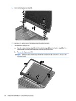
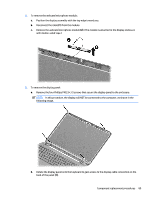
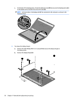
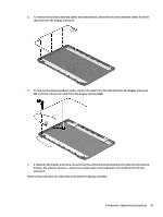
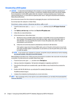
2. To remove the webcam/microphone module: a. Position the display assembly with the top edge toward you. b. Disconnect the cable (1) from the module. c. Remove the webcam/microphone module (2). (The module is attached to the display enclosure with double-sided tape.) 3. To remove the display panel: a. Remove the four Phillips PM2.5×3.5 screws that secure the display panel to the enclosure. NOTE: In this procedure, the display will NOT be connected to the computer, as shown in the following image. b. Rotate the display panel onto the keyboard to gain access to the display cable connection on the back of the panel (1). Component replacement procedures 89
-
 1
1 -
2
-
3
-
4
-
5
-
6
-
7
-
8
-
9
-
10
-
11
-
12
-
13
-
14
-
15
-
16
-
17
-
18
-
19
-
20
-
21
-
22
-
23
-
24
-
25
-
26
-
27
-
28
-
29
-
30
-
31
-
32
-
33
-
34
-
35
-
36
-
37
-
38
-
39
-
40
-
41
-
42
-
43
-
44
-
45
-
46
-
47
-
48
-
49
-
50
-
51
-
52
-
53
-
54
-
55
-
56
-
57
-
58
-
59
-
60
-
61
-
62
-
63
-
64
-
65
-
66
-
67
-
68
-
69
-
70
-
71
-
72
-
73
-
74
-
75
-
76
-
77
-
78
-
79
-
80
-
81
-
82
-
83
-
84
-
85
-
86
-
87
-
88
-
89
-
90
-
91
-
 92
92 -
 93
93 -
 94
94 -
 95
95 -
 96
96 -
 97
97 -
 98
98 -
 99
99 -
 100
100 -
 101
101 -
 102
102 -
103
-
104
-
105
-
106
-
107
-
108
-
109
-
110
-
111
-
112
-
113
-
114
-
115
-
116
-
117
-
118
-
119
-
120
-
121
-
122
-
123
-
124
-
125
-
126
-
127
-
128
-
129
-
130
-
131
-
132
-
133
-
134
-
135
-
136
-
137
-
138
-
139
-
140
-
141
-
142
-
143
-
144
-
145
-
146
-
147
-
148
 |
 |

2.
To remove the webcam/microphone module:
a.
Position the display assembly with the top edge toward you.
b.
Disconnect the cable
(1)
from the module.
c.
Remove the webcam/microphone module
(2)
. (The module is attached to the display enclosure
with double-sided tape.)
3.
To remove the display panel:
a.
Remove the four Phillips PM2.5×3.5 screws that secure the display panel to the enclosure.
NOTE:
In this procedure, the display will NOT be connected to the computer, as shown in the
following image.
b.
Rotate the display panel onto the keyboard to gain access to the display cable connection on the
back of the panel
(1)
.
Component replacement procedures
89