HP 2000-bf00 HP 2000 Notebook PC Compaq Presario CQ58 Notebook PC Maintenance - Page 57
Power connector, Disconnect the power connector cable
 |
View all HP 2000-bf00 manuals
Add to My Manuals
Save this manual to your list of manuals |
Page 57 highlights
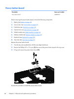
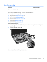
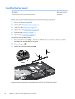
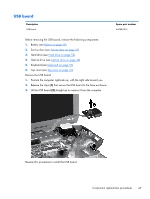
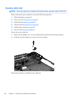
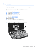
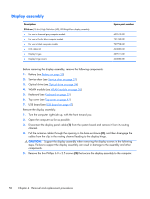
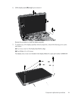
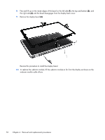
Power connector Description Power connector (includes cable) Spare part number 640891-001 Before removing the power connector cable, remove the following components: 1. Battery (see Battery on page 30) 2. Service door (see Service door on page 31) 3. Hard drive (see Hard drive on page 32) 4. Optical drive (see Optical drive on page 34) 5. Keyboard (see Keyboard on page 39) 6. Top cover (see Top cover on page 41) Remove the power connector: 1. Turn the computer right-side up, with the right side toward you. 2. Disconnect the power connector cable (1) from the system board. 3. Lift the power connector (2) from the clips built into the base enclosure. Reverse this procedure to install the power connector. Component replacement procedures 49
-
 1
1 -
2
-
3
-
4
-
5
-
6
-
7
-
8
-
9
-
10
-
11
-
12
-
13
-
14
-
15
-
16
-
17
-
18
-
19
-
20
-
21
-
22
-
23
-
24
-
25
-
26
-
27
-
28
-
29
-
30
-
31
-
32
-
33
-
34
-
35
-
36
-
37
-
38
-
39
-
40
-
41
-
42
-
43
-
44
-
45
-
46
-
47
-
48
-
49
-
50
-
51
-
 52
52 -
 53
53 -
 54
54 -
 55
55 -
 56
56 -
 57
57 -
 58
58 -
 59
59 -
 60
60 -
 61
61 -
 62
62 -
63
-
64
-
65
-
66
-
67
-
68
-
69
-
70
-
71
-
72
-
73
-
74
-
75
-
76
-
77
-
78
-
79
-
80
-
81
-
82
-
83
-
84
-
85
-
86
-
87
-
88
-
89
-
90
-
91
-
92
-
93
-
94
 |
 |

Power connector
Description
Spare part number
Power connector (includes cable)
640891-001
Before removing the power connector cable, remove the following components:
1.
Battery (see
Battery
on page
30
)
2.
Service door (see
Service door
on page
31
)
3.
Hard drive (see
Hard drive
on page
32
)
4.
Optical drive (see
Optical drive
on page
34
)
5.
Keyboard (see
Keyboard
on page
39
)
6.
Top cover (see
Top cover
on page
41
)
Remove the power connector:
1.
Turn the computer right-side up, with the right side toward you.
2.
Disconnect the power connector cable
(1)
from the system board.
3.
Lift the power connector
(2)
from the clips built into the base enclosure.
Reverse this procedure to install the power connector.
Component replacement procedures
49