HP 2000-bf00 HP 2000 Notebook PC Compaq Presario CQ58 Notebook PC Maintenance - Page 66
When replacing the system board, be sure that the following components are removed from
 |
View all HP 2000-bf00 manuals
Add to My Manuals
Save this manual to your list of manuals |
Page 66 highlights
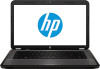
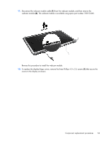
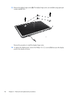
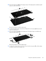
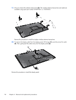
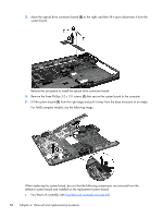
3. Move the optical drive connector board (2) to the right, and then lift it up to disconnect it from the system board. Reverse this procedure to install the optical drive connector board. 4. Remove the three Phillips 3.0 x 2.0 screws (1) that secure the system board to the computer. 5. Lift the system board (2) from the right edge and pull it away from the base enclosure at an angle. For AMD computer models, see the following image. When replacing the system board, be sure that the following components are removed from the defective system board and installed on the replacement system board: ● Fan/heat sink assembly (see Fan/heat sink assembly on page 60) 58 Chapter 4 Removal and replacement procedures
-
 1
1 -
2
-
3
-
4
-
5
-
6
-
7
-
8
-
9
-
10
-
11
-
12
-
13
-
14
-
15
-
16
-
17
-
18
-
19
-
20
-
21
-
22
-
23
-
24
-
25
-
26
-
27
-
28
-
29
-
30
-
31
-
32
-
33
-
34
-
35
-
36
-
37
-
38
-
39
-
40
-
41
-
42
-
43
-
44
-
45
-
46
-
47
-
48
-
49
-
50
-
51
-
52
-
53
-
54
-
55
-
56
-
57
-
58
-
59
-
60
-
 61
61 -
 62
62 -
 63
63 -
 64
64 -
 65
65 -
 66
66 -
 67
67 -
 68
68 -
 69
69 -
 70
70 -
 71
71 -
72
-
73
-
74
-
75
-
76
-
77
-
78
-
79
-
80
-
81
-
82
-
83
-
84
-
85
-
86
-
87
-
88
-
89
-
90
-
91
-
92
-
93
-
94
 |
 |
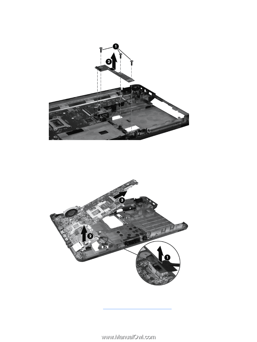
3.
Move the optical drive connector board
(2)
to the right, and then lift it up to disconnect it from the
system board.
Reverse this procedure to install the optical drive connector board.
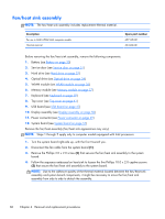
4.
Remove the three Phillips 3.0 x 2.0 screws
(1)
that secure the system board to the computer.
5.
Lift the system board
(2)
from the right edge and pull it away from the base enclosure at an angle.
For AMD computer models, see the following image.
When replacing the system board, be sure that the following components are removed from the
defective system board and installed on the replacement system board:
●
Fan/heat sink assembly (see
Fan/heat sink assembly
on page
60
)
58
Chapter 4
Removal and replacement procedures