HP 2000-bf00 HP 2000 Notebook PC Compaq Presario CQ58 Notebook PC Maintenance - Page 58
Display assembly
 |
View all HP 2000-bf00 manuals
Add to My Manuals
Save this manual to your list of manuals |
Page 58 highlights
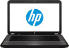
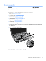
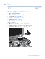
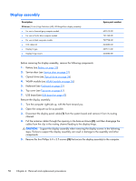
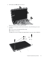
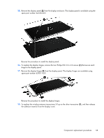
Display assembly Description 39.6-cm (15.6-in) High Definition (HD), LED BrightView display assembly: ● For use in charcoal grey computer models ● For use in Pacific blue computer models ● For use in black computer models ● LCD rubber kit ● Display hinges ● Display hinge covers Spare part number 639512-001 701769-001 707798-001 640882-001 639511-001 640882-001 Before removing the display assembly, remove the following components: 1. Battery (see Battery on page 30) 2. Service door (see Service door on page 31) 3. Optical drive (see Optical drive on page 34) 4. WLAN module (see WLAN module on page 36) 5. Keyboard (see Keyboard on page 39) 6. Top cover (see Top cover on page 41) 7. USB board (see USB board on page 47) Remove the display assembly: 1. Turn the computer right-side up, with the front toward you. 2. Open the computer as far as possible. 3. Disconnect the display panel cable (1) from the system board and remove it from its routing channel. 4. Pull the antenna cables through the opening in the base enclosure (2), and then disengage the cables from the clip in the routing channel leading to the display hinge. CAUTION: Support the display assembly when removing the display screws in the following steps. Failure to support the display assembly can result in damage to the assembly and other components. 5. Remove the five Phillips 6.0 x 2.5 screws (3) that secure the display assembly to the computer. 50 Chapter 4 Removal and replacement procedures
-
 1
1 -
2
-
3
-
4
-
5
-
6
-
7
-
8
-
9
-
10
-
11
-
12
-
13
-
14
-
15
-
16
-
17
-
18
-
19
-
20
-
21
-
22
-
23
-
24
-
25
-
26
-
27
-
28
-
29
-
30
-
31
-
32
-
33
-
34
-
35
-
36
-
37
-
38
-
39
-
40
-
41
-
42
-
43
-
44
-
45
-
46
-
47
-
48
-
49
-
50
-
51
-
52
-
 53
53 -
 54
54 -
 55
55 -
 56
56 -
 57
57 -
 58
58 -
 59
59 -
 60
60 -
 61
61 -
 62
62 -
 63
63 -
64
-
65
-
66
-
67
-
68
-
69
-
70
-
71
-
72
-
73
-
74
-
75
-
76
-
77
-
78
-
79
-
80
-
81
-
82
-
83
-
84
-
85
-
86
-
87
-
88
-
89
-
90
-
91
-
92
-
93
-
94
 |
 |