HP 2730p HP EliteBook 2730p Notebook PC - Maintenance and Service Guide - Page 69
System board, Display assembly see
 |
UPC - 884420401063
View all HP 2730p manuals
Add to My Manuals
Save this manual to your list of manuals |
Page 69 highlights
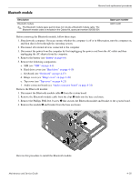
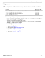
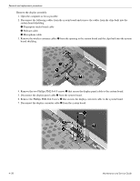
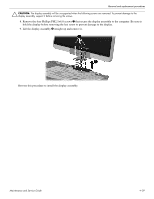
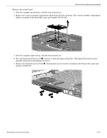
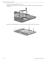
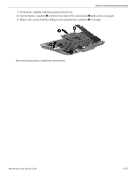
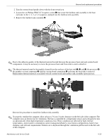
Removal and replacement procedures System board ✎ The system board spare part kit includes replacement thermal material. Description Equipped with Intel Core2 Duo SL9400 1.86-GHz processor, 1066-MHz FSB, and 6-MB L2 cache Equipped with Intel Core2 Duo SL9300 1.60-GHz processor, 1066-MHz FSB, and 6-MB L2 cache Equipped with Intel Core2 Duo SU9300 1.20-GHz processor, 800-MHz FSB, and 3-MB L2 cache Spare part number 501483-001 501482-001 501481-001 Before removing the system board, follow these steps: 1. Shut down the computer. If you are unsure whether the computer is off or in Hibernation, turn the computer on, and then shut it down through the operating system. 2. Disconnect all external devices connected to the computer. 3. Disconnect the power from the computer by first unplugging the power cord from the AC outlet and then unplugging the AC adapter from the computer. 4. Remove the battery (see "Battery" on page 4-8). 5. Remove the following components: a. SIM (see "SIM" on page 4-9) b. Hard drive cover (see "Hard drive" on page 4-10) c. Keyboard (see "Keyboard" on page 4-17) d. Hinge cover (see "Hinge cover" on page 4-20) e. Top cover (see "Top cover" on page 4-21) f. Display assembly (see "Display assembly" on page 4-27) When replacing the system board, be sure that the following components are removed from the defective system board and installed on the replacement system board: ■ SIM (see "SIM" on page 4-9) ■ WLAN module (see "WLAN module" on page 4-12) ■ WWAN module (see "WWAN module" on page 4-15) ■ Memory modules (see "Memory module" on page 4-16) ■ RTC battery (see "RTC battery" on page 4-23) ■ Fan/heat sink assembly (see "Fan/heat sink assembly" on page 4-34) ■ Modem module (see "Modem module" on page 4-36) 4-30 Maintenance and Service Guide
-
 1
1 -
2
-
3
-
4
-
5
-
6
-
7
-
8
-
9
-
10
-
11
-
12
-
13
-
14
-
15
-
16
-
17
-
18
-
19
-
20
-
21
-
22
-
23
-
24
-
25
-
26
-
27
-
28
-
29
-
30
-
31
-
32
-
33
-
34
-
35
-
36
-
37
-
38
-
39
-
40
-
41
-
42
-
43
-
44
-
45
-
46
-
47
-
48
-
49
-
50
-
51
-
52
-
53
-
54
-
55
-
56
-
57
-
58
-
59
-
60
-
61
-
62
-
63
-
 64
64 -
 65
65 -
 66
66 -
 67
67 -
 68
68 -
 69
69 -
 70
70 -
 71
71 -
 72
72 -
 73
73 -
 74
74 -
75
-
76
-
77
-
78
-
79
-
80
-
81
-
82
-
83
-
84
-
85
-
86
-
87
-
88
-
89
-
90
-
91
-
92
-
93
-
94
-
95
-
96
-
97
-
98
-
99
-
100
-
101
-
102
-
103
-
104
-
105
-
106
-
107
-
108
-
109
-
110
-
111
-
112
-
113
-
114
-
115
-
116
-
117
-
118
-
119
-
120
-
121
-
122
-
123
 |
 |