HP 6120G/XG HP ProCurve Series 6120 Blade Switches Installation and Getting St - Page 47
Technology distance specifications, Mode Conditioning Patch Cord, Installing the Patch Cord, Table 8.
 |
View all HP 6120G/XG manuals
Add to My Manuals
Save this manual to your list of manuals |
Page 47 highlights
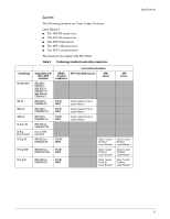
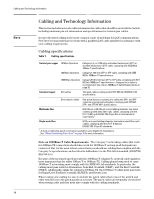
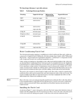
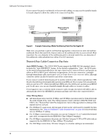
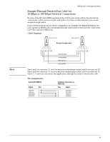
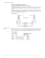
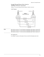
Note Cabling and Technology Information Technology distance specifications Table 8. Technology distance specifications Technology 1000-T 1000-SX 1000-LX 10-Gig CX4 10-Gig Direct Attach 10-Gig SR 10-Gig LRM 10-Gig LR Supported cable type twisted-pair copper multimode fiber multimode fiber single mode fiber twinaxial copper twinaxial copper multimode fiber multimode fiber single mode fiber Multimode fiber modal bandwidth N/A 160 MHz*km 200 MHz*km 400 MHz*km 500 MHz*km 400 MHz*km 500 MHz*km N/A N/A N/A 160 MHz*km 200 MHz*km 400 MHz*km 500 MHz*km 2000 MHz*km 400 MHz*km 500 MHz*km N/A Supported distances up to 100 meters 2 - 220 meters 2 - 275 meters 2 - 500 meters 2 - 550 meters 2 - 550 meters 2 - 550 meters 2 - 10,000 meters up to 15 meters (various lengths offered) 2 - 26 meters 2 - 33 meters 2 - 66 meters 2 - 82 meters 2 - 300 meters 0.5 - 100 meters 0.5 - 220 meters 2 - 10,000 meters Mode Conditioning Patch Cord The following information applies to installations in which multimode fiber-optic cables are connected to a Gigabit-LX port. Multimode cable has a design characteristic called "Differential Mode Delay", which requires the transmission signals be "conditioned" to compensate for the cable design and thus prevent resulting transmission errors. Under certain circumstances, depending on the cable used and the lengths of the cable runs, an external Mode Conditioning Patch Cord may need to be installed between the Gigabit-LX transmitting device and the multimode network cable to provide the transmission conditioning. If you experience a high number of transmission errors on those ports, usually CRC or FCS errors, you may need to install one of these patch cords between the fiber-optic port in your switch and your multimode fiber-optic network cabling, at both ends of the network link. The patch cord consists of a short length of single mode fiber cable coupled to graded-index multimode fiber cable on the transmit side, and only multimode cable on the receive side. The section of single mode fiber is connected in such a way that it minimizes the effects of the differential mode delay in the multimode cable. Most of the time, if you are using good quality graded-index multimode fiber cable that adheres to the standards listed in Appendix B, there should not be a need to use mode conditioning patch cords in your network. This is especially true if the fiber runs in your network are relatively short. Installing the Patch Cord As shown in Figure 7, connect the patch cord to the ProCurve transceiver with the section of single mode fiber plugged in to the Tx (transmit) port. Then, connect the other end of the patch cord to your network cabling patch panel, or directly to the network multimode fiber. 39
-
 1
1 -
2
-
3
-
4
-
5
-
6
-
7
-
8
-
9
-
10
-
11
-
12
-
13
-
14
-
15
-
16
-
17
-
18
-
19
-
20
-
21
-
22
-
23
-
24
-
25
-
26
-
27
-
28
-
29
-
30
-
31
-
32
-
33
-
34
-
35
-
36
-
37
-
38
-
39
-
40
-
41
-
 42
42 -
 43
43 -
 44
44 -
 45
45 -
 46
46 -
 47
47 -
 48
48 -
 49
49 -
 50
50 -
 51
51 -
 52
52 -
53
-
54
-
55
-
56
-
57
-
58
-
59
-
60
-
61
-
62
 |
 |