HP 8000 Hardware Reference Guide - HP Compaq 8000 Elite Convertible Minitower - Page 39
CAUTION, Installing a Hard Drive into the Hard Drive Bay
 |
UPC - 884420665106
View all HP 8000 manuals
Add to My Manuals
Save this manual to your list of manuals |
Page 39 highlights
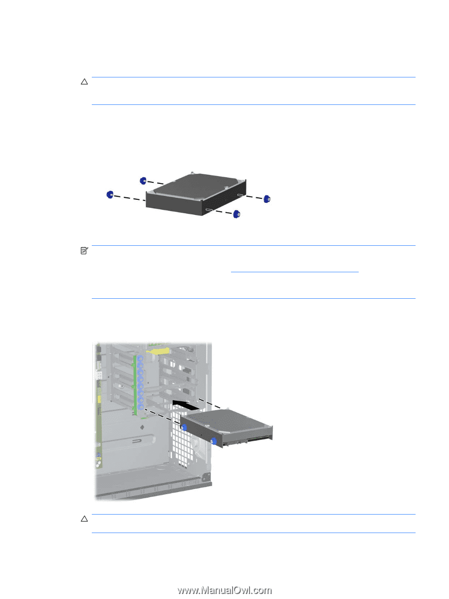
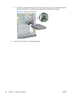
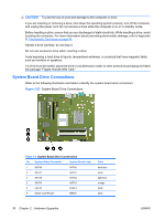
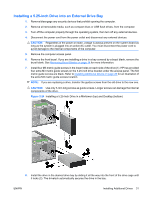
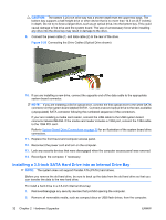
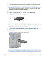
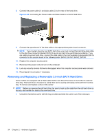
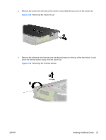
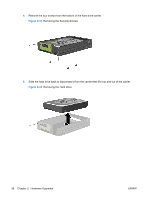
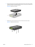
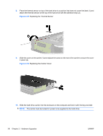
3. Turn off the computer properly through the operating system, then turn off any external devices. 4. Disconnect the power cord from the power outlet and disconnect any external devices. CAUTION: Regardless of the power-on state, voltage is always present on the system board as long as the system is plugged into an active AC outlet. You must disconnect the power cord to avoid damage to the internal components of the computer. 5. Remove the computer access panel. 6. Install four 6-32 isolation mounting guide screws, two on each side of the drive. Figure 2-26 Installing the Hard Drive Guide Screws NOTE: The hard drive uses 6-32 isolation mounting guide screws. Eight extra guide screws are installed on the hard drive bracket under the access panel. The HP-supplied isolation mounting guide screws are silver and blue. Refer to Installing Additional Drives on page 29 for an illustration of the extra 6-32 isolation mounting guide screws location. If you are replacing a drive, transfer the guides screws from the old drive to the new one. 7. Slide the hard drive down into the drive cage until it locks. The drivelock automatically secures the drive in the bay. Figure 2-27 Installing a Hard Drive into the Hard Drive Bay CAUTION: Make sure the guide screws line up with the guide slots in the drive cage. The use of unnecessary force when installing any drive into the drive bay may result in damage to the drive. ENWW Installing Additional Drives 33
-
 1
1 -
2
-
3
-
4
-
5
-
6
-
7
-
8
-
9
-
10
-
11
-
12
-
13
-
14
-
15
-
16
-
17
-
18
-
19
-
20
-
21
-
22
-
23
-
24
-
25
-
26
-
27
-
28
-
29
-
30
-
31
-
32
-
33
-
 34
34 -
 35
35 -
 36
36 -
 37
37 -
 38
38 -
 39
39 -
 40
40 -
 41
41 -
 42
42 -
 43
43 -
 44
44 -
45
-
46
-
47
-
48
-
49
-
50
-
51
-
52
-
53
-
54
-
55
-
56
-
57
-
58
-
59
-
60
-
61
-
62
-
63
-
64
 |
 |