HP 8100 Technical Reference Guide: HP Compaq 8100 Elite Series Business Deskto - Page 60
USB Connector, 6.2 USB Cable Data, Table 5-6., USB Connector Pinout, USB Cable Length Data
 |
View all HP 8100 manuals
Add to My Manuals
Save this manual to your list of manuals |
Page 60 highlights
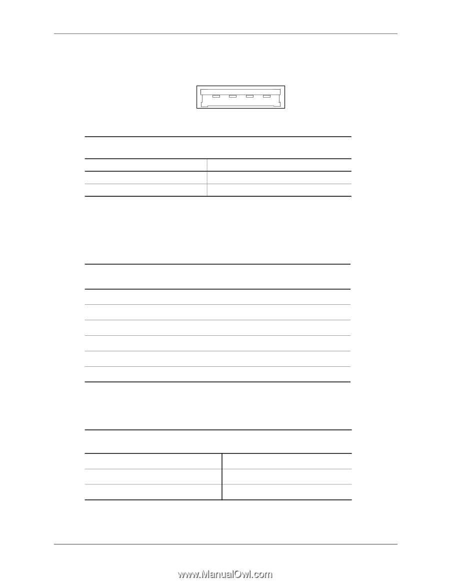
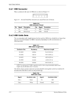
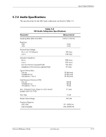
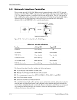
Input/Output Interfaces 5.6.1 USB Connector These systems provide type-A USB ports as shown in Figure 5-7. 1 2 3 4 Figure 5-7. Universal Serial Bus Connector (as viewed from rear of chassis) Table 5-6. USB Connector Pinout Pin Signal Description Pin Signal Description 1 Vcc +5 VDC 3 USB+ Data (plus) 2 USB- Data (minus) 4 GND Ground 5.6.2 USB Cable Data The recommended cable length between the host and the USB device should be no longer than sixteen feet for full-channel (12 MB/s) operation, depending on cable specification (see following table). Table 5-7. USB Cable Length Data Conductor Size Resistance Maximum Length 20 AWG 0.036 Ω 16.4 ft (5.00 m) 22 AWG 0.057 Ω 9.94 ft (3.03 m) 24 AWG 0.091 Ω 6.82 ft (2.08 m) 26 AWG 0.145 Ω 4.30 ft (1.31 m) 28 AWG 0.232 Ω 2.66 ft (0.81 m) NOTE: For sub-channel (1.5 MB/s) operation and/or when using sub-standard cable shorter lengths may be allowable and/or necessary. The shield, chassis ground, and power ground should be tied together at the host end but left unconnected at the device end to avoid ground loops. Table 5-8. USB Color Code Signal Insulation color Signal Insulation Color Data + Green Vcc Red Data - White Ground Black 5-10 www.hp.com Technical Reference Guide
-
 1
1 -
2
-
3
-
4
-
5
-
6
-
7
-
8
-
9
-
10
-
11
-
12
-
13
-
14
-
15
-
16
-
17
-
18
-
19
-
20
-
21
-
22
-
23
-
24
-
25
-
26
-
27
-
28
-
29
-
30
-
31
-
32
-
33
-
34
-
35
-
36
-
37
-
38
-
39
-
40
-
41
-
42
-
43
-
44
-
45
-
46
-
47
-
48
-
49
-
50
-
51
-
52
-
53
-
54
-
 55
55 -
 56
56 -
 57
57 -
 58
58 -
 59
59 -
 60
60 -
 61
61 -
 62
62 -
 63
63 -
 64
64 -
 65
65 -
66
-
67
-
68
-
69
-
70
-
71
-
72
-
73
-
74
-
75
-
76
-
77
-
78
-
79
-
80
-
81
-
82
-
83
-
84
-
85
-
86
-
87
-
88
-
89
-
90
-
91
-
92
-
93
-
94
-
95
-
96
-
97
-
98
-
99
-
100
-
101
-
102
-
103
-
104
-
105
-
106
-
107
-
108
-
109
-
110
-
111
-
112
 |
 |