HP 8100 Technical Reference Guide: HP Compaq 8100 Elite Series Business Deskto - Page 75
Power and Signal Distribution, Introduction, Power Distribution
 |
View all HP 8100 manuals
Add to My Manuals
Save this manual to your list of manuals |
Page 75 highlights
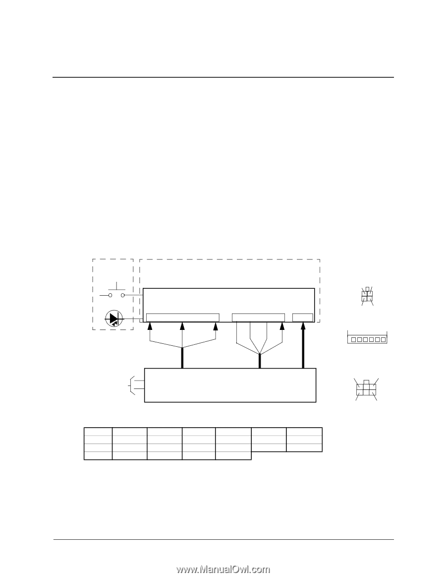
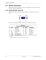
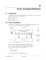
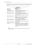
7 Power and Signal Distribution 7.1 Introduction This chapter describes the power supplies and discusses the methods of general power and signal distribution. Topics covered in this chapter include: ■ Power distribution (7.2) ■ Power Control (7.3) ■ Signal distribution (7.4) 7.2 Power Distribution These systems use a common power source power supply unit contained within the system chassis. Figure 7-1 shows the block diagram for power generation. Front Bezel Power Button Power On System Board Power Control Logic, DC/DC Converter & Voltage Regulators P1 +12 Vmain +12 Vsb -12 V P2 PS Fan Fan On Cmd Spd P3 Pwr Good +12 Vcpu P3 34 12 P2 6 54 3 21 90 - 264 VAC Power Supply Unit NOTE: Return (RTN or ground) not shown. P1 4 6 1 3 Conn P1 P2 P3 Pin 1 RTN FANcmd RTN Pin 2 RTN Fan Speed RTN Pin 3 -12 V PS On +12 Vcpu Pin 4 +12 Vmain Pwr Good +12 Vcpu Pin 5 +12 Vmain RTN Pin 6 +12 Vsb RTN NOTES: Connectors not shown to scale. All + and - values are VDC. RTN = Return (signal ground) Figure 7-1. Power Distribution and Cabling, Block Diagram Technical Reference Guide www.hp.com 7-1
-
 1
1 -
2
-
3
-
4
-
5
-
6
-
7
-
8
-
9
-
10
-
11
-
12
-
13
-
14
-
15
-
16
-
17
-
18
-
19
-
20
-
21
-
22
-
23
-
24
-
25
-
26
-
27
-
28
-
29
-
30
-
31
-
32
-
33
-
34
-
35
-
36
-
37
-
38
-
39
-
40
-
41
-
42
-
43
-
44
-
45
-
46
-
47
-
48
-
49
-
50
-
51
-
52
-
53
-
54
-
55
-
56
-
57
-
58
-
59
-
60
-
61
-
62
-
63
-
64
-
65
-
66
-
67
-
68
-
69
-
 70
70 -
 71
71 -
 72
72 -
 73
73 -
 74
74 -
 75
75 -
 76
76 -
 77
77 -
 78
78 -
 79
79 -
 80
80 -
81
-
82
-
83
-
84
-
85
-
86
-
87
-
88
-
89
-
90
-
91
-
92
-
93
-
94
-
95
-
96
-
97
-
98
-
99
-
100
-
101
-
102
-
103
-
104
-
105
-
106
-
107
-
108
-
109
-
110
-
111
-
112
 |
 |