HP 8100 Technical Reference Guide: HP Compaq 8100 Elite Series Business Deskto - Page 81
Signal Distribution, Table 7-6., System Board Connector, Indicator, and Switch Designations
 |
View all HP 8100 manuals
Add to My Manuals
Save this manual to your list of manuals |
Page 81 highlights
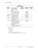
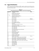
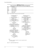
Power and Signal Distribution 7.5 Signal Distribution Table 7-6 lists the reference designators for LEDs, connectors, indicators, and switches used on the system boards for systems covered in this guide. Unless otherwise indicated, components are present on all system boards. Table 7-6. System Board Connector, Indicator, and Switch Designations Designator Component function Notes CR1 +5 VDC LED E1 E14 E49 / JP49 J9 Descriptor table override header SPI ROM boot block header Password clear header / jumper Stacked RJ-45 & dual USB connectors J10 Stacked quad USB connectors J20 PCI 2.3 connector J21 PCI 2.3 connector CMT only J22 PCI 2.3 connector CMT only J31 PCIe x1 connector J32 PCIe x1 connector J41 PCIe x16 graphics connector J42 PCIe x4 graphics (x16) connector J50 Parallel port J68 Stacked keyboard, mouse PS/2 connectors J69 VGA monitor DB-15 connector J78 Stacked audio line-in, headphone/line-out 1/8" jacks P1 Power supply header P2 Power supply header P3 Power supply header P5 Control panel (power button, power LED) header P6 Internal speaker header P8 CPU fan header P9 Chassis fan, primary, header P23 Front panel audio header P24 Front panel USB header P52 Serial port, secondary, header P53 Serial port, primary connector P54 Serial port, primary header SFF only P60 SATA0 (controller 1, primary master) connector (dark blue) P61 SATA1 (controller 1, secondary master) connector (white) P62 SATA2 (controller 1, primary slave) connector (light blue) P63 SATA3 (controller 1, secondary slave) connector (orange) CMT only P64 SATA4 / eSATA (controller 2, primary master) connector (black) P124 Hood lock header P125 Hood sense header P126 Parallel port header P150 Internal USB header P151 P160 Internal USB header SATA power Technical Reference Guide www.hp.com 7-7
-
 1
1 -
2
-
3
-
4
-
5
-
6
-
7
-
8
-
9
-
10
-
11
-
12
-
13
-
14
-
15
-
16
-
17
-
18
-
19
-
20
-
21
-
22
-
23
-
24
-
25
-
26
-
27
-
28
-
29
-
30
-
31
-
32
-
33
-
34
-
35
-
36
-
37
-
38
-
39
-
40
-
41
-
42
-
43
-
44
-
45
-
46
-
47
-
48
-
49
-
50
-
51
-
52
-
53
-
54
-
55
-
56
-
57
-
58
-
59
-
60
-
61
-
62
-
63
-
64
-
65
-
66
-
67
-
68
-
69
-
70
-
71
-
72
-
73
-
74
-
75
-
 76
76 -
 77
77 -
 78
78 -
 79
79 -
 80
80 -
 81
81 -
 82
82 -
 83
83 -
 84
84 -
 85
85 -
 86
86 -
87
-
88
-
89
-
90
-
91
-
92
-
93
-
94
-
95
-
96
-
97
-
98
-
99
-
100
-
101
-
102
-
103
-
104
-
105
-
106
-
107
-
108
-
109
-
110
-
111
-
112
 |
 |