HP Blackbird 002-01A HP Blackbird Gaming System - Getting Started Guide - Page 12
Connector/LED/Button, Description and function continued
 |
View all HP Blackbird 002-01A manuals
Add to My Manuals
Save this manual to your list of manuals |
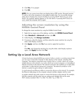
Page 12 highlights
Connector/LED/Button Description and function (continued) Audio Line Out (to powered speakers). Microphone (pink) connector. Headphones (green) connector. Optical Out/Microphone In to connect to a microphone. The Mic connector also functions as a center/subwoofer Line Out when a multichannel audio configuration is activated. IEEE 1394a connector. This 6-pin connector provides high-speed connectivity for audio/video devices, storage peripherals, PCs, or portable devices with very fast transfer rates. Coaxial S/PDIF Out (orange) port connects an external audio output device via an optical S/PDIF cable. Optical Out connector. Optical SPDIF output connects to the Optical In on a set of digital speakers. The digital speakers would then split up the audio signal to the correct speaker. Power cord connector. Computer power LED. Power switch to be turned on before the power button on the front of the computer is pressed. Power button. Press the power button after the power switch on the back of the computer is turned on. LAN 1 and LAN 2 (RJ-45) connectors. Supported by NV Gigabit LAN controller, this connector allows gigabit connection to a local area network (LAN) through a network hub. 4 Getting Started (features vary by model)
-
 1
1 -
2
-
3
-
4
-
5
-
6
-
 7
7 -
 8
8 -
 9
9 -
 10
10 -
 11
11 -
 12
12 -
 13
13 -
 14
14 -
 15
15 -
 16
16 -
 17
17 -
18
-
19
-
20
-
21
-
22
-
23
-
24
-
25
-
26
-
27
-
28
-
29
-
30
-
31
-
32
-
33
-
34
-
35
-
36
-
37
-
38
-
39
-
40
-
41
-
42
-
43
-
44
-
45
-
46
-
47
-
48
-
49
-
50
-
51
-
52
-
53
-
54
-
55
-
56
-
57
-
58
-
59
-
60
-
61
-
62
-
63
-
64
-
65
-
66
-
67
-
68
-
69
-
70
-
71
-
72
-
73
-
74
-
75
-
76
-
77
-
78
-
79
-
80
-
81
-
82
-
83
-
84
-
85
-
86
-
87
-
88
-
89
-
90
-
91
-
92
-
93
-
94
-
95
-
96
-
97
-
98
-
99
-
100
-
101
-
102
-
103
-
104
-
105
-
106
-
107
-
108
-
109
-
110
-
111
-
112
-
113
-
114
-
115
-
116
-
117
-
118
-
119
-
120
-
121
-
122
-
123
-
124
-
125
-
126
-
127
-
128
-
129
-
130
-
131
-
132
-
133
-
134
-
135
-
136
-
137
-
138
-
139
-
140
-
141
-
142
-
143
-
144
-
145
-
146
-
147
-
148
-
149
-
150
-
151
-
152
-
153
-
154
-
155
-
156
-
157
-
158
-
159
-
160
-
161
-
162
-
163
-
164
 |
 |
