HP Cluster Platform Hardware Kits v2010 HP 16/18-Port Cable Management Kit Ins - Page 11
InfiniBand Cable Secured with a Releasable Cable Tie, Caution
 |
View all HP Cluster Platform Hardware Kits v2010 manuals
Add to My Manuals
Save this manual to your list of manuals |
Page 11 highlights
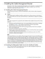
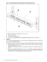
Figure 5 InfiniBand Cable Secured with a Releasable Cable Tie 1 2 Caution: The releasable cable tie should only be hand tight. Do not use a cable tie installation tool and do not over tighten the releasable cable tie or it might damage the InfiniBand cable. 4. Leaving approximately 1/4 inch to 3/8 inch coming out of the buckle, clip the excess from the releasable cable tie. Use one of the clipped-off pieces of cable tie as a tightness gauge (see callout 1 in Figure 6) to check that there is room to allow the InfiniBand cable (callout 4 in Figure 6) to move freely in the releasable cable tie loop (callout 3 in Figure 6) that is secured to the cable management bracket (callout 2 in Figure 6) with a push button mount (not shown in Figure 6). Figure 6 Gauging the Tightness of the Releasable Cable Tie Loop 3 4 2 1 5. Repeat steps 4 and 5 to secure the remaining InfiniBand cables. 6. Route the InfiniBand cables to the side of the rack and secure them either upward or downward in the cable management plate. Be sure not to exceed the cable manufacturer's recommended bend radius for each InfiniBand cable as you route them in the rack. 3.2 Installing the Releasable Cable Ties for the InfiniBand Cables 11
-
 1
1 -
2
-
3
-
4
-
5
-
 6
6 -
 7
7 -
 8
8 -
 9
9 -
 10
10 -
 11
11 -
 12
12 -
 13
13 -
 14
14
 |
 |
