HP Cluster Platform Hardware Kits v2010 HP 16/18-Port Cable Management Kit Ins - Page 9
Installing the Cable Management Bracket
 |
View all HP Cluster Platform Hardware Kits v2010 manuals
Add to My Manuals
Save this manual to your list of manuals |
Page 9 highlights
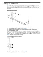
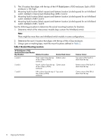
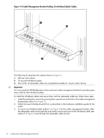
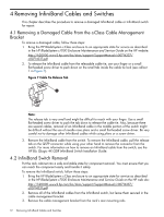
3 Installing the Cable Management Bracket The location of the cable management bracket depends on the rack position occupied by the HP BladeSystem c-Class enclosure. The InfiniBand switch might be installed in any or all of the interconnect module bays identified in Table 2. 3.1 Installing the Cable Management Bracket Use the following procedure to install the HP BladeSystem c-Class enclosure cable management bracket: Caution: When performing the installation procedure, extend only one c-Class enclosure no more than a few inches from the rack at any time. Ensure that the rack is stable before you begin the installation procedure. Note: One cable management kit is required for each InfiniBand switch installed in the rear of the c-Class enclosure. 1. Starting from the lowest bracket location, and using the fastener locations that you identified and marked in Chapter 2, clip a cage nut into the back of each rear rack column. 2. Hook the bracket onto the square cutouts in the rack column. 3. Fasten the bracket to the rear rack columns by using two M6 pan-head screws and tighten them to the specified torque. 4. If more than one bracket is required, repeat Step 1. 5. Slide the c-Class enclosure back into the rack and secure it at the front of the rack as specified in the installation instructions for the enclosure. 6. If necessary, attach the second bracket once the first switch (lowest switch in the c7000 enclosure) is cabled and tie-wrapped. Note: HP recommends that you only install the cable management bracket for the lowest InfiniBand switch in the c-Class enclosure and complete the cable installation. Doing so makes it easier to install the releasable cable ties for each of the InfiniBand cables. Once the releasable cable ties are installed for the InfiniBand cables coming from the switch installed in the lowest interconnect module bay, you must install the next cable management bracket and releasable cable ties for the next InfiniBand switch. It is necessary to complete the installation for the lowest bracket first because there is not enough space between the two brackets to secure the releasable cable ties for the lower bracket when two or more brackets must be installed. 3.2 Installing the Releasable Cable Ties for the InfiniBand Cables Figure 4 shows the holes in the bracket that are used in the cable management bracket for an InfiniBand switch with 16 external uplink ports. 3.1 Installing the Cable Management Bracket 9
-
 1
1 -
2
-
3
-
 4
4 -
 5
5 -
 6
6 -
 7
7 -
 8
8 -
 9
9 -
 10
10 -
 11
11 -
 12
12 -
 13
13 -
 14
14
 |
 |
