HP Cluster Platform Hardware Kits v2010 HP 16/18-Port Cable Management Kit Ins - Page 7
Aligning the Bracket
 |
View all HP Cluster Platform Hardware Kits v2010 manuals
Add to My Manuals
Save this manual to your list of manuals |
Page 7 highlights
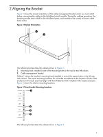
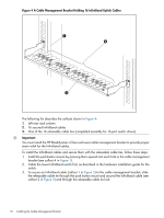
2 Aligning the Bracket Figure 2 shows the correct orientation of the cable management bracket which you must install before connecting the cables to the InfiniBand switch module. During the cabling procedure, the bracket provides strain relief for the InfiniBand ports, and maintains the correct minimum cable bend radius. Figure 2 Bracket Orientation 1 2 The following list describes the callouts shown in Figure 2: 1. Mounting hook installed in one of the mounting holes in the rack's rear left column 2. Cable management bracket Callout 1 shows the bracket's mounting hook installed in one of the square holes in the left rear rack column. The actual mounting locations for a bracket are relevant to the location of the c-Class enclosure in the rack, and must align with the InfiniBand switch installed in the c-Class enclosure. Figure 3 shows the relative mounting locations. Figure 3 Three Bracket Mounting Locations 1 U10 U9 U8 2 U7 3 U6 4 The following list describes the callouts shown in Figure 3: 7
-
 1
1 -
 2
2 -
 3
3 -
 4
4 -
 5
5 -
 6
6 -
 7
7 -
 8
8 -
 9
9 -
 10
10 -
 11
11 -
 12
12 -
13
-
14
 |
 |
