HP Cluster Platform Hardware Kits v2010 Linux Clusters QsNetII Cable Managemen - Page 11
Cabling the Interconnect, Bundling and Routing the Cables
 |
View all HP Cluster Platform Hardware Kits v2010 manuals
Add to My Manuals
Save this manual to your list of manuals |
Page 11 highlights
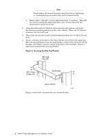
Figure 7: Cabling the Interconnect 2 1 3 zk-2084 5. Slide the cable forward until its connector aligns with the port (callout 3 in Figure 7), and secure the cable by pushing only on the metal connector body (callout 2 in Figure 7). Ensure that you keep the connector level and square with the port as you insert it. 6. Repeat steps 2 through 5 for all remaining cables. If you are installing an interconnect into the upper part of the rack, proceed to step 7. Otherwise, the installation procedure is compete at this point. 7. If you are installing an interconnect into the upper part of a dual-interconnect IBB, you must route the cables down the guide plate and support them by using the cable straps as shown in Figure 2, callout 4. Use the appropriate length strap for the cable bundle diameter. You need only use enough straps to keep the cable bundles tight to the plate, so that they do not interfere with the servicing of interconnect components. Figure 8 shows how to attach one of the straps to the cable guide plate. Figure 8: Bundling and Routing the Cables Y X Z zk-2079 Starting from the top of the cable guide plate and working downwards, use the following procedure to attach the straps: a. Using the leftmost screw holes in the cable guide plate, attach the strap by using an M5 x 10 mm Torx screw (callout 1). b. Feed the end of the strap through the cutout in the left of the cable guide plate (callout 2). QsNetII Cable Management Kit Installation Guide 9
-
 1
1 -
2
-
3
-
4
-
5
-
 6
6 -
 7
7 -
 8
8 -
 9
9 -
 10
10 -
 11
11 -
 12
12 -
 13
13
 |
 |
