HP Cluster Platform Hardware Kits v2010 Linux Clusters QsNetII Cable Managemen - Page 12
Servicing the Interconnect
 |
View all HP Cluster Platform Hardware Kits v2010 manuals
Add to My Manuals
Save this manual to your list of manuals |
Page 12 highlights
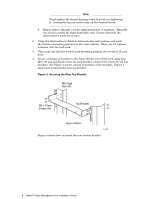
c. When securing cables with the strap, loop the end of the strap through the metal D ring and secure it with the hook-and-loop closure (callout 3). d. Repeat steps a through c for the remaining straps. 11 Servicing the Interconnect To service the interconnect, use the following procedures. Replacing a Cable Use the following procedure to replace a malfunctioning cable: 1. Consult the documentation for your interconnect to determine the link (cable) removal prerequisites. For example, you should determine the correct procedure for shutting down and powering off nodes or any interconnect components. 2. Route a replacement cable from the node to the interconnect, following the cable routing and bundling instructions for your cluster. 3. After bringing the link to an appropriate state, disconnect the malfunctioning cable. Note If you are not ready to connect a replacement cable immediately, cover any active interconnect ports with an EMI-shielded cap. 4. Hook the cable into the cable management bar and connect it to the interconnect port. 5. To replace a cable in the top interconnect of a dual-interconnect IBB, secure the new cable to the cable guide plate. See Section 10 for the cable strapping procedure. HP recommends that you do not attempt to remove defective cables unless it is necessary to return them for servicing. Label the cable as defective and secure it out of the way of other cables and components. Servicing an Interconnect's Port Card Use the following procedure to service an interconnect's port cards: 1. Consult the documentation for your cluster and interconnect to determine the card removal prerequisites. For example, you should determine whether or not you need to shut down and power off the associated nodes or any interconnect components. 2. Disconnect all cable plugs from the interconnect ports. 3. At the top of the cable management bar, pull down the spring-loaded retainer pin and rotate it until the pin is locked in the retracted position, as shown in Figure 5. 4. Swing the cable management bar down 90 degrees, allowing the cables to hang freely below it or loop onto the floor. 5. Perform the required service operation on the interconnect. 6. When the service operation is complete, swing the cable management bar up 90 degrees and release the spring-loaded retainer pin. Ensure that the pin is inserted firmly into the upper bracket. 7. Reconnect the cables to their respective ports. 10 QsNetII Cable Management Kit Installation Guide
-
 1
1 -
2
-
3
-
4
-
5
-
6
-
 7
7 -
 8
8 -
 9
9 -
 10
10 -
 11
11 -
 12
12 -
 13
13
 |
 |
