HP Cluster Platform Introduction v2010 HP Cluster Platform Server and Workstat - Page 157
Supported Storage, 4.2.3 Removing the HP ProLiant BL35p from the Sleeve
 |
View all HP Cluster Platform Introduction v2010 manuals
Add to My Manuals
Save this manual to your list of manuals |
Page 157 highlights
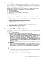
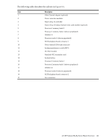
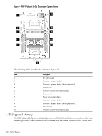
4.2.2 Supported Storage The HP ProLiant BL35p supports up to up to two 60 GB parallel ATA hard disk drives. The drive cage assembly lower drive bay is designated as the primary hard drive. The physical aspect of inserting and removing a disk drive is discussed in the document that ships with the drive and in the HP ProLiant BL35p Server Blade User Guide. In addition to the hard drives, the HP ProLiant BL35p has SAN storage capability. It can be configured for SAN connectivity when used with the following components: • Fibre Channel adapter • SAN-compatible interconnect • SFP transceivers (included with the Dual Port FC Adapter) • Optical FC cables • Supported SAN and associated software For more detailed SAN configuration information for the server blade, see the following documents: • The model-specific QuickSpecs document located on the HP ProLiant p-Class server blade products web page: http://www.hp.com/products/servers/proliant-bl/p-class/info • The HP StorageWorks SAN documentation: http://h18006.www1.hp.com/storage/index.html Search for the SAN product required, and navigate to technical documentation. • The HP BladeSystem p-Class storage web page: http://www.hp.com/go/bladesystem/storage 4.2.3 Removing the HP ProLiant BL35p from the Sleeve To remove an HP ProLiant BL35p from the HP BladeSystem p-Class sleeve in the blade enclosure, follow these steps: • Back up all server blade data. • Power down the server blade, using one of the following methods: - Press the Power On/Standby button on the server blade front panel. Be sure that the server blade is in Standby mode by observing that the power LED is amber. This process may take 30 seconds, during which time some internal circuitry remains active. - Use the virtual power button feature in the iLO Remote Console to power down the server blade from a remote location. After initiating a manual or virtual power down command, be sure that the server blade goes into Standby mode by observing that the power LED is amber. Important: When the server blade is in Standby mode, auxiliary power is still being provided. To remove all power from the server blade, remove the server blade from the server blade enclosure. Removing the sleeve from the server blade enclosure is not necessary. Important: Remote power procedures require the most recent firmware for the power enclosure and server blade enclosure management modules. • Remove the server blade from the sleeve, as shown in Figure 4-3. 4.2 HP ProLiant BL35p Server Blade Overview 157
-
 1
1 -
2
-
3
-
4
-
5
-
6
-
7
-
8
-
9
-
10
-
11
-
12
-
13
-
14
-
15
-
16
-
17
-
18
-
19
-
20
-
21
-
22
-
23
-
24
-
25
-
26
-
27
-
28
-
29
-
30
-
31
-
32
-
33
-
34
-
35
-
36
-
37
-
38
-
39
-
40
-
41
-
42
-
43
-
44
-
45
-
46
-
47
-
48
-
49
-
50
-
51
-
52
-
53
-
54
-
55
-
56
-
57
-
58
-
59
-
60
-
61
-
62
-
63
-
64
-
65
-
66
-
67
-
68
-
69
-
70
-
71
-
72
-
73
-
74
-
75
-
76
-
77
-
78
-
79
-
80
-
81
-
82
-
83
-
84
-
85
-
86
-
87
-
88
-
89
-
90
-
91
-
92
-
93
-
94
-
95
-
96
-
97
-
98
-
99
-
100
-
101
-
102
-
103
-
104
-
105
-
106
-
107
-
108
-
109
-
110
-
111
-
112
-
113
-
114
-
115
-
116
-
117
-
118
-
119
-
120
-
121
-
122
-
123
-
124
-
125
-
126
-
127
-
128
-
129
-
130
-
131
-
132
-
133
-
134
-
135
-
136
-
137
-
138
-
139
-
140
-
141
-
142
-
143
-
144
-
145
-
146
-
147
-
148
-
149
-
150
-
151
-
 152
152 -
 153
153 -
 154
154 -
 155
155 -
 156
156 -
 157
157 -
 158
158 -
 159
159 -
 160
160 -
 161
161 -
 162
162 -
163
-
164
-
165
-
166
-
167
-
168
-
169
-
170
-
171
-
172
-
173
-
174
-
175
-
176
-
177
-
178
-
179
-
180
-
181
-
182
-
183
-
184
-
185
-
186
-
187
-
188
-
189
-
190
-
191
-
192
-
193
-
194
-
195
-
196
-
197
-
198
-
199
-
200
-
201
-
202
-
203
-
204
-
205
-
206
-
207
-
208
-
209
-
210
-
211
-
212
-
213
-
214
-
215
-
216
-
217
-
218
-
219
-
220
-
221
-
222
-
223
-
224
-
225
-
226
-
227
-
228
-
229
-
230
-
231
-
232
-
233
-
234
-
235
-
236
-
237
-
238
-
239
-
240
-
241
-
242
-
243
-
244
-
245
-
246
-
247
-
248
 |
 |