HP Cluster Platform Introduction v2010 HP Cluster Platform Server and Workstat - Page 38
PCI Slot Assignments, HP Integrity rx2620 Rear Panel
 |
View all HP Cluster Platform Introduction v2010 manuals
Add to My Manuals
Save this manual to your list of manuals |
Page 38 highlights
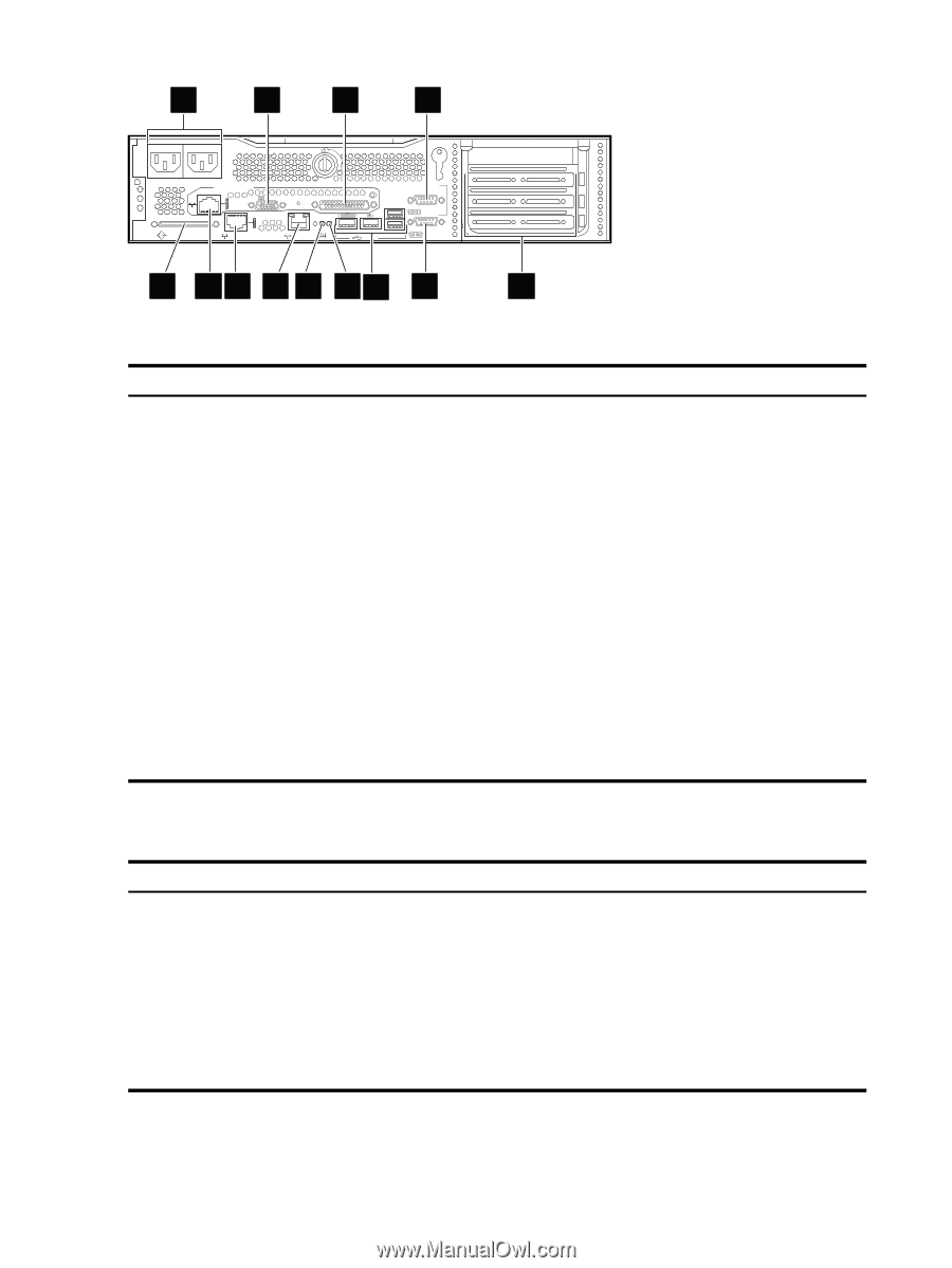
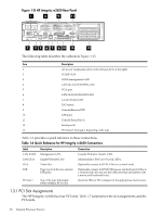
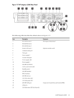
Figure 1-15 HP Integrity rx2620 Rear Panel 1 5 9 11 WARNING Unplug all power cords from system before servicing PWR PWR 2 1 Management Card LAN 10/100 VGA Automatic Internal SCSI Termination SCSI LVD/SE LAN Gb A MP RESET CONSOLE / REMOTE / UPS LAN Gb B TOC USB CONSOLE SERIAL A SERIAL B 2 3 4 6 7 8 10 12 13 The following table describes the callouts in Figure 1-15. Item Description 1 AC power receptacles (AC2 on the left and AC1 on the right) 2 LVD/SE SCSI 3 10/100 management LAN 4 LAN Gb A (10/100/1000 LAN) 5 VGA port 6 LAN Gb B (10/100/1000 LAN) 7 Locator button/LED 8 ToC button 9 Console/Remote/UPS 10 USB ports 11 Console/Serial Port A 12 Serial port B 13 PCI slots (1 through 4, beginning at the top) Table 1-6 provides a quick reference to these connections. Table 1-6 Quick Reference for HP Integrity rx2620 Connections Label LAN 10/100 LAN Gb A VGA USB Description Management LAN Gigabit Ethernet LAN Video Out Upper port of the two stacked USB ports PCI slot 1 Top of the four full-length 64-bit/133MHz PCI-X slot Connection Console ProCurve Switch, CES1. Administrative ProCurve Switch, AES1. Optionally connect to KVM, if this is a control node. Optionally connect to KVM USB mouse and keyboard, if this is a control node. (Do not use the USB ports that are labeled with a mouse and keyboard icon.) Install an HBA or HCA adapter for the appropriate interconnect. 1.3.1 PCI Slot Assignments The HP Integrity rx2620 has four PCI slots. Table 1-7 summarizes the slot assignments and the PCI cards. 38 Itanium Processor Servers
-
 1
1 -
2
-
3
-
4
-
5
-
6
-
7
-
8
-
9
-
10
-
11
-
12
-
13
-
14
-
15
-
16
-
17
-
18
-
19
-
20
-
21
-
22
-
23
-
24
-
25
-
26
-
27
-
28
-
29
-
30
-
31
-
32
-
 33
33 -
 34
34 -
 35
35 -
 36
36 -
 37
37 -
 38
38 -
 39
39 -
 40
40 -
 41
41 -
 42
42 -
 43
43 -
44
-
45
-
46
-
47
-
48
-
49
-
50
-
51
-
52
-
53
-
54
-
55
-
56
-
57
-
58
-
59
-
60
-
61
-
62
-
63
-
64
-
65
-
66
-
67
-
68
-
69
-
70
-
71
-
72
-
73
-
74
-
75
-
76
-
77
-
78
-
79
-
80
-
81
-
82
-
83
-
84
-
85
-
86
-
87
-
88
-
89
-
90
-
91
-
92
-
93
-
94
-
95
-
96
-
97
-
98
-
99
-
100
-
101
-
102
-
103
-
104
-
105
-
106
-
107
-
108
-
109
-
110
-
111
-
112
-
113
-
114
-
115
-
116
-
117
-
118
-
119
-
120
-
121
-
122
-
123
-
124
-
125
-
126
-
127
-
128
-
129
-
130
-
131
-
132
-
133
-
134
-
135
-
136
-
137
-
138
-
139
-
140
-
141
-
142
-
143
-
144
-
145
-
146
-
147
-
148
-
149
-
150
-
151
-
152
-
153
-
154
-
155
-
156
-
157
-
158
-
159
-
160
-
161
-
162
-
163
-
164
-
165
-
166
-
167
-
168
-
169
-
170
-
171
-
172
-
173
-
174
-
175
-
176
-
177
-
178
-
179
-
180
-
181
-
182
-
183
-
184
-
185
-
186
-
187
-
188
-
189
-
190
-
191
-
192
-
193
-
194
-
195
-
196
-
197
-
198
-
199
-
200
-
201
-
202
-
203
-
204
-
205
-
206
-
207
-
208
-
209
-
210
-
211
-
212
-
213
-
214
-
215
-
216
-
217
-
218
-
219
-
220
-
221
-
222
-
223
-
224
-
225
-
226
-
227
-
228
-
229
-
230
-
231
-
232
-
233
-
234
-
235
-
236
-
237
-
238
-
239
-
240
-
241
-
242
-
243
-
244
-
245
-
246
-
247
-
248
 |
 |