HP DL740 HP F8 Architecture Technology Brief - Page 5
Hot-Plug RAID Memory, Memory Configuration, RAID Memory Striping, Memory, Configuration, RAID Memory
 |
UPC - 808736765770
View all HP DL740 manuals
Add to My Manuals
Save this manual to your list of manuals |
Page 5 highlights
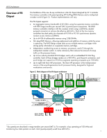
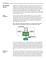
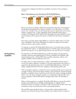
HP F8 Architecture Hot-Plug RAID Memory Memory Configuration RAID Memory Striping Probably the most significant improvement in the F8 architecture is the addition of Hot-Plug RAID Memory, which increases availability, scalability, and fault tolerance in industrystandard servers. The F8 memory controllers provide greatly increased memory bandwidth to handle the Xeon MP bus speeds, which are four times greater than the P6 bus speeds. The F8 architecture supplies hot-add, hot-replace, and hot-upgrade capabilities. It allows the detection of otherwise undetectable memory errors, which provides a level of data protection far greater than parity or error correcting code (ECC) solutions. HP Hot-Plug RAID Memory enables the memory subsystem to withstand a complete memory device failure and to continue operating normally. The F8 chipset uses five memory controllers designed by HP to control five cartridges of industry-standard PC100 or PC133 SDRAM. Within each cartridge, a dual memory controller uses 1.06-GB/s paths into two separate channels of memory (Figure 3). This gives a total bandwidth of 2.12 GB/s within each memory cartridge. External to the memory cartridge, the memory controllers interface with the crossbar switch using a 200-MHz, double-pumped, point-to-point connection. Thus, the memory network interface has an effective data transfer rate of 400 MT/s. Figure 3. Block diagram showing memory configuration for a single memory cartridge. Each dual memory controller has two independent paths to the two-way interleaved memory channels. Memory Cartridge Even Odd 1.06 GB/s F8 Dual Memory Controller 1.06 GB/s Memory Network Interface 400 MT/s F8 Crossbar Switch The two memory channels are cache-line interleaved; they share a common address range. As a memory controller performs a write transaction, cache lines with even addresses go to one memory channel and cache lines with odd addresses simultaneously go to the other. Cache-line interleaving is advantageous because memory accesses are typically localized: certain address ranges tend to be accessed more frequently than others, creating "hot spots" in the memory. Interleaving allows the memory controller to split the heavily used locations between the two channels, since roughly half of all accesses will be even and half will be odd. When the memory controller needs to write data to memory, it splits the cache line of data into four blocks. Then each block is written, or striped, across either the even or odd channel of memory in the memory cartridge. A RAID engine in the F8 chipset calculates the Boolean exclusive-OR (XOR) parity information, which is stored on a fifth cartridge dedicated to parity (Figure 4). The four data cartridges and the parity cartridge are each protected by ECC. With the redundant parity data, complete and correct data can be rebuilt from the 5
-
 1
1 -
 2
2 -
 3
3 -
 4
4 -
 5
5 -
 6
6 -
 7
7 -
 8
8 -
 9
9 -
 10
10 -
 11
11 -
12
-
13
-
14
 |
 |
