HP Dv3-1075us HP Pavilion dv3 Entertainment PC - Maintenance and Service Guide - Page 41
WLAN module, Loosen the Phillips PM2.5×6.0 screws - black
 |
UPC - 884420737087
View all HP Dv3-1075us manuals
Add to My Manuals
Save this manual to your list of manuals |
Page 41 highlights
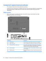
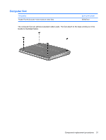
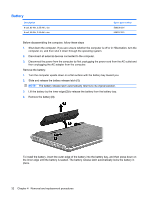
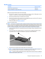
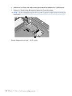
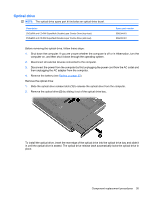
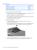
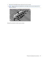
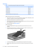
WLAN module Description Broadcom 802.11b/g WLAN module Broadcom 4322AGN 802.11a/b/g/n WLAN module Spare part number 459263-001 487330-001 Before removing the WLAN module, follow these steps: 1. Shut down the computer. If you are unsure whether the computer is off or in Hibernation, turn the computer on, and then shut it down through the operating system. 2. Disconnect all external devices connected to the computer. 3. Disconnect the power from the computer by first unplugging the power cord from the AC outlet and then unplugging the AC adapter from the computer. 4. Remove the battery (see Battery on page 32). Remove the WLAN module: NOTE: To prevent an unresponsive system, replace the wireless module only with a wireless module authorized for use in the computer by the governmental agency that regulates wireless devices in your country or region. If you replace the module and then receive a warning message, remove the module to restore computer functionality, and then contact technical support through Help and Support. 1. Loosen the Phillips PM2.5×6.0 screws (1) that secure the wireless module compartment cover to the computer. 2. Lift the rear edge of the cover (2), swing it up, and remove the cover (3). The wireless module compartment cover is included in the Plastics Kit, spare part number 506953-001. 3. Disconnect the two WLAN antenna cables (1) from the WLAN module. NOTE: The black WLAN antenna cable is connected to the WLAN module "Main" terminal. The white WLAN antenna cable is connected to the WLAN module "Aux" terminal. NOTE: Computer models equipped with an 802.11ab/g/n WLAN module will have an additional wireless antenna cable, yellow in color. Component replacement procedures 33
-
 1
1 -
2
-
3
-
4
-
5
-
6
-
7
-
8
-
9
-
10
-
11
-
12
-
13
-
14
-
15
-
16
-
17
-
18
-
19
-
20
-
21
-
22
-
23
-
24
-
25
-
26
-
27
-
28
-
29
-
30
-
31
-
32
-
33
-
34
-
35
-
 36
36 -
 37
37 -
 38
38 -
 39
39 -
 40
40 -
 41
41 -
 42
42 -
 43
43 -
 44
44 -
 45
45 -
 46
46 -
47
-
48
-
49
-
50
-
51
-
52
-
53
-
54
-
55
-
56
-
57
-
58
-
59
-
60
-
61
-
62
-
63
-
64
-
65
-
66
-
67
-
68
-
69
-
70
-
71
-
72
-
73
-
74
-
75
-
76
-
77
-
78
-
79
-
80
-
81
-
82
-
83
-
84
-
85
-
86
-
87
-
88
-
89
-
90
-
91
-
92
-
93
-
94
-
95
-
96
-
97
-
98
-
99
-
100
-
101
-
102
-
103
-
104
-
105
-
106
-
107
-
108
-
109
-
110
-
111
-
112
-
113
-
114
 |
 |
