HP Dv3-1075us HP Pavilion dv3 Entertainment PC - Maintenance and Service Guide - Page 54
from the display enclosure. The display panel is available using the, from the display panel cable.
 |
UPC - 884420737087
View all HP Dv3-1075us manuals
Add to My Manuals
Save this manual to your list of manuals |
Page 54 highlights
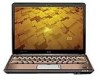
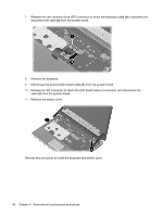
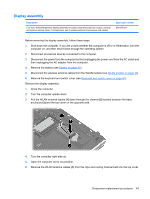
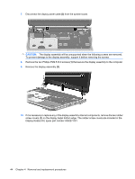
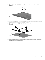
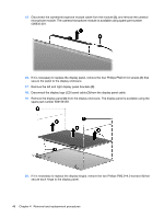
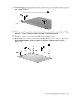
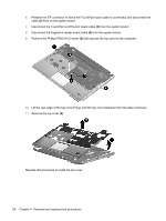
15. Disconnect the camera/microphone module cable from the module (2), and remove the camera/ microphone module. The camera/microphone module is available using spare part number 506930-001. 16. If it is necessary to replace the display panel, remove the four Phillips PM2.5×4.0 screws (1) that secure the panel to the display enclosure. 17. Remove the left and right display panel brackets (2). 18. Disconnect the display logo LED board cable (3) from the display panel cable. 19. Remove the display panel (4) from the display enclosure. The display panel is available using the spare part number 506156-001. 20. If it is necessary to replace the display hinges, remove the two Phillips PM2.0×4.0 screws (1) that secure each hinge to the display panel. 46 Chapter 4 Removal and replacement procedures
-
 1
1 -
2
-
3
-
4
-
5
-
6
-
7
-
8
-
9
-
10
-
11
-
12
-
13
-
14
-
15
-
16
-
17
-
18
-
19
-
20
-
21
-
22
-
23
-
24
-
25
-
26
-
27
-
28
-
29
-
30
-
31
-
32
-
33
-
34
-
35
-
36
-
37
-
38
-
39
-
40
-
41
-
42
-
43
-
44
-
45
-
46
-
47
-
48
-
 49
49 -
 50
50 -
 51
51 -
 52
52 -
 53
53 -
 54
54 -
 55
55 -
 56
56 -
 57
57 -
 58
58 -
 59
59 -
60
-
61
-
62
-
63
-
64
-
65
-
66
-
67
-
68
-
69
-
70
-
71
-
72
-
73
-
74
-
75
-
76
-
77
-
78
-
79
-
80
-
81
-
82
-
83
-
84
-
85
-
86
-
87
-
88
-
89
-
90
-
91
-
92
-
93
-
94
-
95
-
96
-
97
-
98
-
99
-
100
-
101
-
102
-
103
-
104
-
105
-
106
-
107
-
108
-
109
-
110
-
111
-
112
-
113
-
114
 |
 |
