HP Dv7-3060us HP Pavilion dv7 Entertainment PC - Maintenance and Service Guide - Page 62
Four Phillips PM2.5×6.0 screws., Lift and release the bottom of the display enclosure
 |
UPC - 884962549155
View all HP Dv7-3060us manuals
Add to My Manuals
Save this manual to your list of manuals |
Page 62 highlights
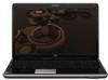
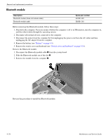
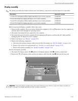
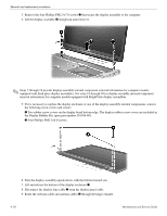
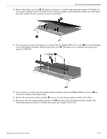
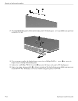
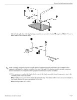
Removal and replacement procedures 3. Remove the four Phillips PM2.5×7.0 screws 1 that secure the display assembly to the computer. 4. Lift the display assembly 2 straight up and remove it. ✎ Steps 5 through 18 provide display assembly internal component removal information for computer models equipped with flush glass display assemblies. See steps 19 through 30 for display assembly internal component removal information for computer models equipped with BrightView display assemblies. 5. If it is necessary to replace the display enclosure or any of the display assembly internal components, remove the following screw covers and screws: 1 Two rubber screw covers on the display bezel bottom edge. The display rubber screw covers are included in the Display Rubber Kit, spare part number 516308-001. 2 Four Phillips PM2.5×6.0 screws. 6. Turn the display assembly upside down, with the bottom toward you. 7. Lift and release the bottom of the display enclosure 1. 8. Disconnect the display logo cable 2 from the display panel cable. 9. Route the webcam cable and antenna cables 3 through the hinge channel. 4-26 Maintenance and Service Guide
-
 1
1 -
2
-
3
-
4
-
5
-
6
-
7
-
8
-
9
-
10
-
11
-
12
-
13
-
14
-
15
-
16
-
17
-
18
-
19
-
20
-
21
-
22
-
23
-
24
-
25
-
26
-
27
-
28
-
29
-
30
-
31
-
32
-
33
-
34
-
35
-
36
-
37
-
38
-
39
-
40
-
41
-
42
-
43
-
44
-
45
-
46
-
47
-
48
-
49
-
50
-
51
-
52
-
53
-
54
-
55
-
56
-
 57
57 -
 58
58 -
 59
59 -
 60
60 -
 61
61 -
 62
62 -
 63
63 -
 64
64 -
 65
65 -
 66
66 -
 67
67 -
68
-
69
-
70
-
71
-
72
-
73
-
74
-
75
-
76
-
77
-
78
-
79
-
80
-
81
-
82
-
83
-
84
-
85
-
86
-
87
-
88
-
89
-
90
-
91
-
92
-
93
-
94
-
95
-
96
-
97
-
98
-
99
-
100
-
101
-
102
-
103
-
104
-
105
-
106
-
107
-
108
-
109
-
110
-
111
-
112
-
113
-
114
-
115
-
116
-
117
-
118
-
119
-
120
-
121
-
122
-
123
-
124
-
125
-
126
-
127
-
128
-
129
-
130
-
131
-
132
-
133
-
134
-
135
-
136
-
137
-
138
-
139
-
140
 |
 |
