HP Dv7-3060us HP Pavilion dv7 Entertainment PC - Maintenance and Service Guide - Page 70
Top cover, Display assembly see
 |
UPC - 884962549155
View all HP Dv7-3060us manuals
Add to My Manuals
Save this manual to your list of manuals |
Page 70 highlights
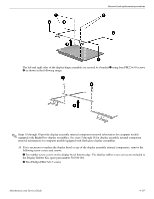
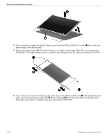
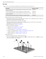
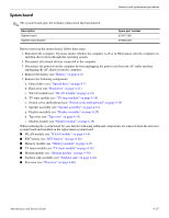
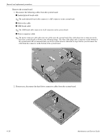
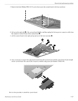
Removal and replacement procedures Top cover ✎ The top cover kit includes TouchPad and cable, LED board and cable, and switch cover. Description For use only with white computer models equipped with a fingerprint reader; includes fingerprint reader board For use only with white computer models not equipped with a fingerprint reader For use only with black computer models equipped with a fingerprint reader; includes fingerprint reader board For use only with black computer models not equipped with a fingerprint reader Spare part number 516299-001 516360-001 519267-001 519268-001 Before removing the top cover, follow these steps: 1. Shut down the computer. If you are unsure whether the computer is off or in Hibernation, turn the computer on, and then shut it down through the operating system. 2. Disconnect all external devices connected to the computer. 3. Disconnect the power from the computer by first unplugging the power cord from the AC outlet and then unplugging the AC adapter from the computer. 4. Remove the battery (see "Battery" on page 4-6). 5. Remove the following components: a. Optical drive (see "Optical drive" on page 4-7) b. Hard drive (see "Hard drive" on page 4-11) c. TV tuner module (see "TV tuner module" on page 4-18) d. Switch cover and keyboard (see "Switch cover and keyboard" on page 4-19) e. Speaker assembly (see "Speaker assembly" on page 4-23) f. Display assembly (see "Display assembly" on page 4-25) Remove the top cover: 1. Turn the computer upside down, with the front toward you. 2. Remove the 3 Phillips 2.5×4.0 silver broadhead screws 1 and 11 Phillips PM2.5×7.0 screws 2 that secure the top cover to the bottom of the computer. 4-34 Maintenance and Service Guide
-
 1
1 -
2
-
3
-
4
-
5
-
6
-
7
-
8
-
9
-
10
-
11
-
12
-
13
-
14
-
15
-
16
-
17
-
18
-
19
-
20
-
21
-
22
-
23
-
24
-
25
-
26
-
27
-
28
-
29
-
30
-
31
-
32
-
33
-
34
-
35
-
36
-
37
-
38
-
39
-
40
-
41
-
42
-
43
-
44
-
45
-
46
-
47
-
48
-
49
-
50
-
51
-
52
-
53
-
54
-
55
-
56
-
57
-
58
-
59
-
60
-
61
-
62
-
63
-
64
-
 65
65 -
 66
66 -
 67
67 -
 68
68 -
 69
69 -
 70
70 -
 71
71 -
 72
72 -
 73
73 -
 74
74 -
 75
75 -
76
-
77
-
78
-
79
-
80
-
81
-
82
-
83
-
84
-
85
-
86
-
87
-
88
-
89
-
90
-
91
-
92
-
93
-
94
-
95
-
96
-
97
-
98
-
99
-
100
-
101
-
102
-
103
-
104
-
105
-
106
-
107
-
108
-
109
-
110
-
111
-
112
-
113
-
114
-
115
-
116
-
117
-
118
-
119
-
120
-
121
-
122
-
123
-
124
-
125
-
126
-
127
-
128
-
129
-
130
-
131
-
132
-
133
-
134
-
135
-
136
-
137
-
138
-
139
-
140
 |
 |
