HP ENVY 15-u400 Maintenance and Service Guide - Page 37
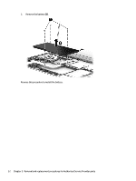
Remove the 12 Phillips PM2.5×6.0 screws, When you lift the top cover
 |
View all HP ENVY 15-u400 manuals
Add to My Manuals
Save this manual to your list of manuals |
Page 37 highlights
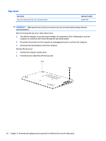
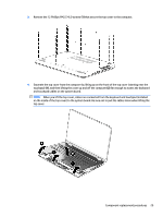
3. Remove the 12 Phillips PM2.5×6.0 screws (1) that secure the top cover to the computer. 4. Separate the top cover from the computer by lifting up on the front of the top cover (starting near the touchpad) (1), and then lifting the cover up and off the computer (2) far enough to access the keyboard and touchpad cables on the system board. NOTE: When you lift the top cover, cables are connected from the keyboard and touchpad (installed on the inside of the top cover) to the system board. Be sure not to pull the cables loose when lifting the top cover. Component replacement procedures 29
-
 1
1 -
2
-
3
-
4
-
5
-
6
-
7
-
8
-
9
-
10
-
11
-
12
-
13
-
14
-
15
-
16
-
17
-
18
-
19
-
20
-
21
-
22
-
23
-
24
-
25
-
26
-
27
-
28
-
29
-
30
-
31
-
 32
32 -
 33
33 -
 34
34 -
 35
35 -
 36
36 -
 37
37 -
 38
38 -
 39
39 -
 40
40 -
 41
41 -
 42
42 -
43
-
44
-
45
-
46
-
47
-
48
-
49
-
50
-
51
-
52
-
53
-
54
-
55
-
56
-
57
-
58
-
59
-
60
-
61
-
62
-
63
-
64
-
65
-
66
-
67
-
68
-
69
-
70
-
71
-
72
-
73
-
74
-
75
-
76
-
77
-
78
-
79
-
80
-
81
-
82
-
83
-
84
-
85
-
86
-
87
-
88
-
89
-
90
-
91
-
92
-
93
-
94
-
95
-
96
 |
 |
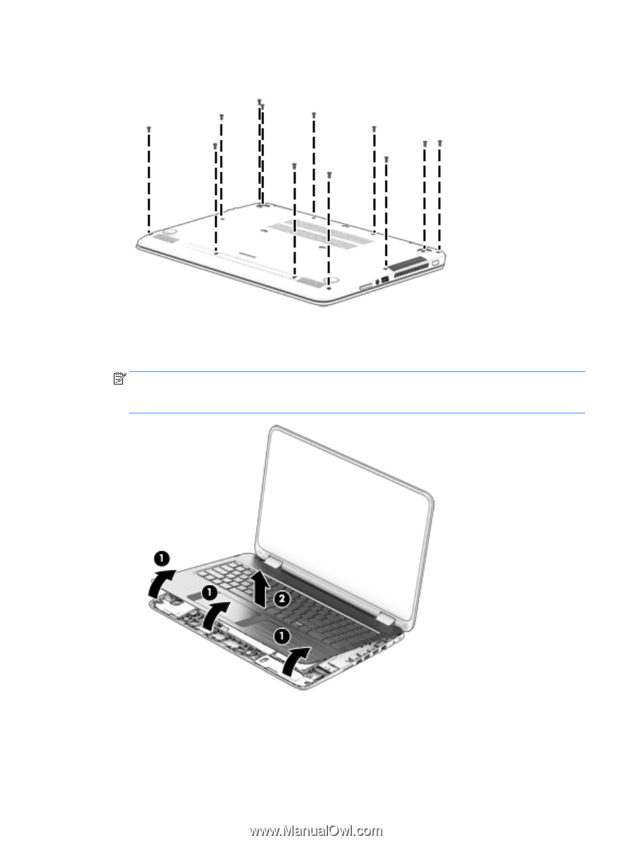
3.
Remove the 12 Phillips PM2.5×6.0 screws
(1)
that secure the top cover to the computer.
4.
Separate the top cover from the computer by lifting up on the front of the top cover (starting near the
touchpad)
(1)
, and then lifting the cover up and off the computer
(2)
far enough to access the keyboard
and touchpad cables on the system board.
NOTE:
When you lift the top cover, cables are connected from the keyboard and touchpad (installed
on the inside of the top cover) to the system board. Be sure not to pull the cables loose when lifting the
top cover.
Component replacement procedures
29