HP ENVY 15-u400 Maintenance and Service Guide - Page 63
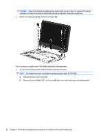
Disconnect the cable, Position the display bezel/display panel assembly upside-down.
 |
View all HP ENVY 15-u400 manuals
Add to My Manuals
Save this manual to your list of manuals |
Page 63 highlights
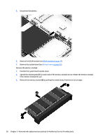
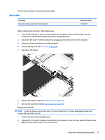
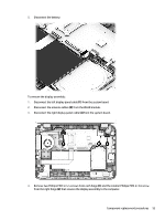
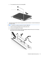
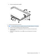
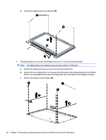
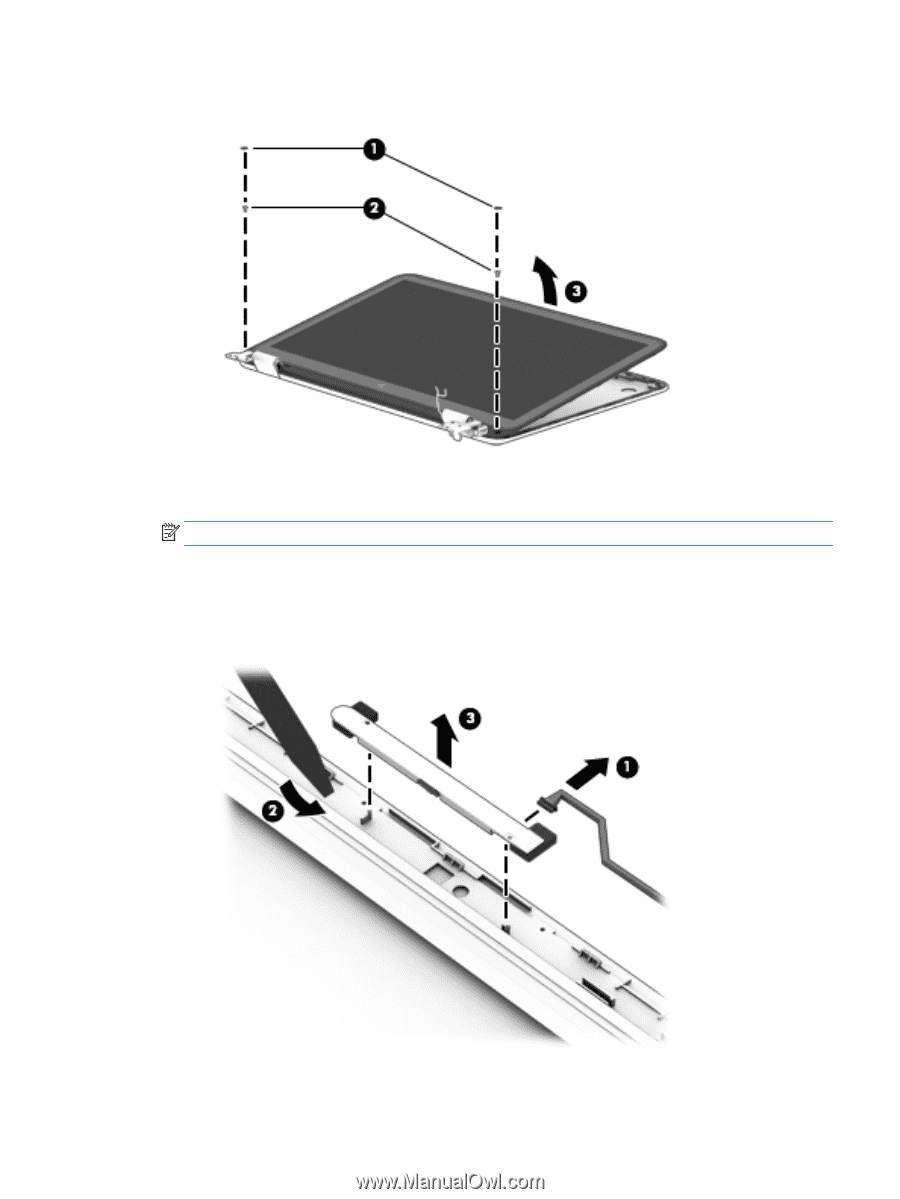
c. Pry to separate the enclosure from the display (3). 2. The webcam and microphone module is mounted on the inside of the bezel. To remove the webcam and microphone module: NOTE: The webcam is available using spare part number 768040-001. a. Position the display bezel/display panel assembly upside-down. b. Disconnect the cable (1) from the module. c. Use a thin tool to lift the webcam module to disengage the adhesive that secures it to the display (2), and then remove the webcam module (3). Component replacement procedures 55
-
 1
1 -
2
-
3
-
4
-
5
-
6
-
7
-
8
-
9
-
10
-
11
-
12
-
13
-
14
-
15
-
16
-
17
-
18
-
19
-
20
-
21
-
22
-
23
-
24
-
25
-
26
-
27
-
28
-
29
-
30
-
31
-
32
-
33
-
34
-
35
-
36
-
37
-
38
-
39
-
40
-
41
-
42
-
43
-
44
-
45
-
46
-
47
-
48
-
49
-
50
-
51
-
52
-
53
-
54
-
55
-
56
-
57
-
 58
58 -
 59
59 -
 60
60 -
 61
61 -
 62
62 -
 63
63 -
 64
64 -
 65
65 -
 66
66 -
 67
67 -
 68
68 -
69
-
70
-
71
-
72
-
73
-
74
-
75
-
76
-
77
-
78
-
79
-
80
-
81
-
82
-
83
-
84
-
85
-
86
-
87
-
88
-
89
-
90
-
91
-
92
-
93
-
94
-
95
-
96
 |
 |
c.
Pry to separate the enclosure from the display
(3)
.
2.
The webcam and microphone module is mounted on the inside of the bezel. To remove the webcam and
microphone module:
NOTE:
The webcam is available using spare part number 768040-001.
a.
Position the display bezel/display panel assembly upside-down.
b.
Disconnect the cable
(1)
from the module.
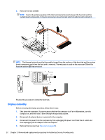
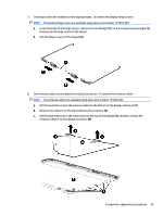
c.
Use a thin tool to lift the webcam module to disengage the adhesive that secures it to the display
(2)
, and then remove the webcam module
(3)
.
Component replacement procedures
55