HP ENVY 15-u400 Maintenance and Service Guide - Page 61
and the smaller Phillips PM2.5×3.6 screw, Remove two Phillips PM2.5×5.5 screws from each hinge
 |
View all HP ENVY 15-u400 manuals
Add to My Manuals
Save this manual to your list of manuals |
Page 61 highlights
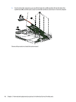
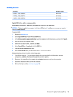
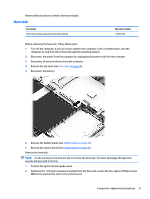
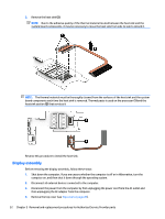
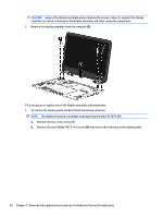
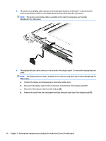
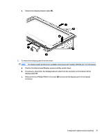
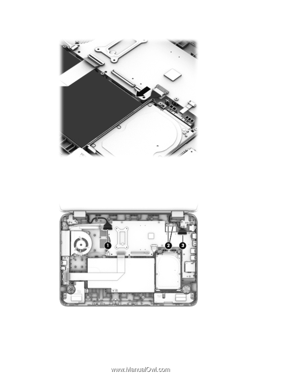
5. Disconnect the battery. To remove the display assembly: 1. Disconnect the left display panel cable (1) from the system board. 2. Disconnect the antenna cables (2) from the WLAN module. 3. Disconnect the right display panel cable (3) from the system board. 4. Remove two Phillips PM2.5×5.5 screws from each hinge (1) and the smaller Phillips PM2.5×3.6 screw from the right hinge (2) that secures the display assembly to the computer. Component replacement procedures 53
-
 1
1 -
2
-
3
-
4
-
5
-
6
-
7
-
8
-
9
-
10
-
11
-
12
-
13
-
14
-
15
-
16
-
17
-
18
-
19
-
20
-
21
-
22
-
23
-
24
-
25
-
26
-
27
-
28
-
29
-
30
-
31
-
32
-
33
-
34
-
35
-
36
-
37
-
38
-
39
-
40
-
41
-
42
-
43
-
44
-
45
-
46
-
47
-
48
-
49
-
50
-
51
-
52
-
53
-
54
-
55
-
 56
56 -
 57
57 -
 58
58 -
 59
59 -
 60
60 -
 61
61 -
 62
62 -
 63
63 -
 64
64 -
 65
65 -
 66
66 -
67
-
68
-
69
-
70
-
71
-
72
-
73
-
74
-
75
-
76
-
77
-
78
-
79
-
80
-
81
-
82
-
83
-
84
-
85
-
86
-
87
-
88
-
89
-
90
-
91
-
92
-
93
-
94
-
95
-
96
 |
 |
5.
Disconnect the battery.
To remove the display assembly:
1.
Disconnect the left display panel cable
(1)
from the system board.
2.
Disconnect the antenna cables
(2)
from the WLAN module.
3.
Disconnect the right display panel cable
(3)
from the system board.
4.
Remove two Phillips PM2.5×5.5 screws from each hinge
(1)
and the smaller Phillips PM2.5×3.6 screw
from the right hinge
(2)
that secures the display assembly to the computer.
Component replacement procedures
53