HP ENVY TouchSmart 15-j119wm HP ENVY 15 Notebook PC and HP ENVY TouchSmart 15 - Page 101
Power button board
 |
View all HP ENVY TouchSmart 15-j119wm manuals
Add to My Manuals
Save this manual to your list of manuals |
Page 101 highlights
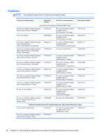
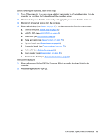
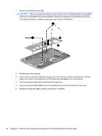
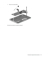
Power button board Description Power button board (includes cable) Spare part number 720553-001 Before removing the power button board, follow these steps: 1. Turn off the computer. If you are unsure whether the computer is off or in Hibernation, turn the computer on, and then shut it down through the operating system. 2. Disconnect the power from the computer by unplugging the power cord from the computer. 3. Disconnect all external devices from the computer. 4. Remove the battery (see Battery on page 41), and then remove the following components: a. Service door (see Service door on page 42) b. mSATA SSD (see mSATA SSD on page 43) c. Hard drive (see Hard drive on page 46) d. Base enclosure (see Base enclosure on page 53) e. System board (see System board on page 64) Remove the power button board: 1. Detach the power button board cable (1) from the top cover. (The power button board cable is attached to the top cover with double-sided tape.) 2. Remove the Phillips PM2.0×2.9 screw (2) that secures the power button board to the top cover. 3. Release the clip (3) that secures the power button board to the top cover. 4. Remove the power button board (4). Reverse this procedure to install the power button board. Component replacement procedures 91
-
 1
1 -
2
-
3
-
4
-
5
-
6
-
7
-
8
-
9
-
10
-
11
-
12
-
13
-
14
-
15
-
16
-
17
-
18
-
19
-
20
-
21
-
22
-
23
-
24
-
25
-
26
-
27
-
28
-
29
-
30
-
31
-
32
-
33
-
34
-
35
-
36
-
37
-
38
-
39
-
40
-
41
-
42
-
43
-
44
-
45
-
46
-
47
-
48
-
49
-
50
-
51
-
52
-
53
-
54
-
55
-
56
-
57
-
58
-
59
-
60
-
61
-
62
-
63
-
64
-
65
-
66
-
67
-
68
-
69
-
70
-
71
-
72
-
73
-
74
-
75
-
76
-
77
-
78
-
79
-
80
-
81
-
82
-
83
-
84
-
85
-
86
-
87
-
88
-
89
-
90
-
91
-
92
-
93
-
94
-
95
-
 96
96 -
 97
97 -
 98
98 -
 99
99 -
 100
100 -
 101
101 -
 102
102 -
 103
103 -
 104
104 -
 105
105 -
 106
106 -
107
-
108
-
109
-
110
-
111
-
112
-
113
-
114
-
115
-
116
-
117
-
118
-
119
-
120
-
121
-
122
-
123
-
124
-
125
-
126
-
127
-
128
-
129
-
130
-
131
 |
 |
