HP ENVY TouchSmart 15-j119wm HP ENVY 15 Notebook PC and HP ENVY TouchSmart 15 - Page 55
Remove the Phillips PM2.0×2.5 screw, Component replacement procedures
 |
View all HP ENVY TouchSmart 15-j119wm manuals
Add to My Manuals
Save this manual to your list of manuals |
Page 55 highlights
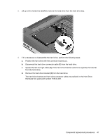
3. Disconnect all external devices from the computer. 4. Remove the battery (see Battery on page 41). 5. Remove the service door (see Service door on page 42). Remove the WLAN module: 1. Identify the WLAN module (1). 2. Disconnect the WLAN antenna cables (1) from the terminals on the WLAN module. NOTE: The WLAN antenna cable labeled "1" connects to the WLAN module "Main" terminal labeled "1". The WLAN antenna cable labeled "2" connects to the WLAN module "Aux" terminal labeled "2". 3. Remove the Phillips PM2.0×2.5 screw (2) that secures the WLAN module to the system board. (The WLAN module tilts up.) 4. Remove the WLAN module (3) by pulling the module away from the slot at an angle. NOTE: If the WLAN antenna cables are not connected to the terminals on the WLAN module, the protective sleeves must be installed on the antenna connectors, as shown in the following illustration. Component replacement procedures 45
-
 1
1 -
2
-
3
-
4
-
5
-
6
-
7
-
8
-
9
-
10
-
11
-
12
-
13
-
14
-
15
-
16
-
17
-
18
-
19
-
20
-
21
-
22
-
23
-
24
-
25
-
26
-
27
-
28
-
29
-
30
-
31
-
32
-
33
-
34
-
35
-
36
-
37
-
38
-
39
-
40
-
41
-
42
-
43
-
44
-
45
-
46
-
47
-
48
-
49
-
 50
50 -
 51
51 -
 52
52 -
 53
53 -
 54
54 -
 55
55 -
 56
56 -
 57
57 -
 58
58 -
 59
59 -
 60
60 -
61
-
62
-
63
-
64
-
65
-
66
-
67
-
68
-
69
-
70
-
71
-
72
-
73
-
74
-
75
-
76
-
77
-
78
-
79
-
80
-
81
-
82
-
83
-
84
-
85
-
86
-
87
-
88
-
89
-
90
-
91
-
92
-
93
-
94
-
95
-
96
-
97
-
98
-
99
-
100
-
101
-
102
-
103
-
104
-
105
-
106
-
107
-
108
-
109
-
110
-
111
-
112
-
113
-
114
-
115
-
116
-
117
-
118
-
119
-
120
-
121
-
122
-
123
-
124
-
125
-
126
-
127
-
128
-
129
-
130
-
131
 |
 |
