HP ENVY Ultrabook CTO 6t-1000 HP Envy 6 Maintenance and Service Guide - Page 54
Memory module, Remove the display panel see
 |
View all HP ENVY Ultrabook CTO 6t-1000 manuals
Add to My Manuals
Save this manual to your list of manuals |
Page 54 highlights
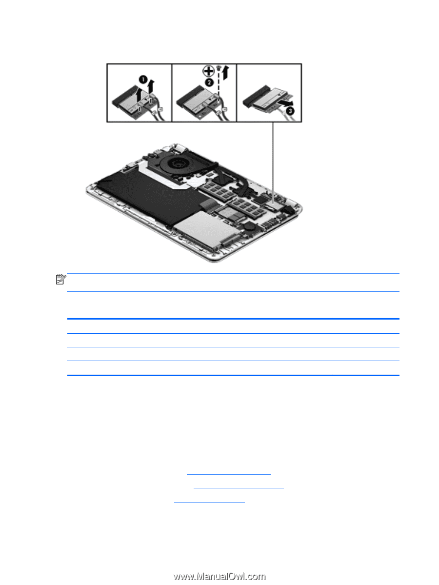
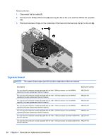
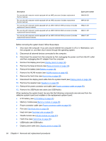
3. Remove the WLAN module by pulling the module away from the slot at an angle (3). NOTE: If the WLAN antennas are not connected to the terminals on the WLAN module, the protective sleeves must be installed on the antenna connectors. Memory module Description 4-GB memory module (PC3, 12800, 1600-MHz) 2-GB memory module (PC3, 12800, 1600-MHz) 8-GB memory module (PC3, 12800, 1600-MHz) Spare part number 641369-005 652972-005 670034-005 Before removing a memory module, follow these steps: 1. Shut down the computer. If you are unsure whether the computer is off or in Hibernation, turn the computer on, and then shut it down through the operating system. 2. Disconnect all external devices connected to the computer. 3. Disconnect the power from the computer by first unplugging the power cord from the AC outlet and then unplugging the AC adapter from the computer. 4. Remove the display panel (see Display panel on page 32). 5. Remove the base enclosure (see Base enclosure on page 34). 6. Remove the keyboard (see Keyboard on page 62). 46 Chapter 4 Removal and replacement procedures
-
 1
1 -
2
-
3
-
4
-
5
-
6
-
7
-
8
-
9
-
10
-
11
-
12
-
13
-
14
-
15
-
16
-
17
-
18
-
19
-
20
-
21
-
22
-
23
-
24
-
25
-
26
-
27
-
28
-
29
-
30
-
31
-
32
-
33
-
34
-
35
-
36
-
37
-
38
-
39
-
40
-
41
-
42
-
43
-
44
-
45
-
46
-
47
-
48
-
 49
49 -
 50
50 -
 51
51 -
 52
52 -
 53
53 -
 54
54 -
 55
55 -
 56
56 -
 57
57 -
 58
58 -
 59
59 -
60
-
61
-
62
-
63
-
64
-
65
-
66
-
67
-
68
-
69
-
70
-
71
-
72
-
73
-
74
-
75
-
76
-
77
-
78
-
79
-
80
-
81
-
82
-
83
-
84
-
85
-
86
-
87
-
88
-
89
-
90
-
91
-
92
-
93
-
94
-
95
-
96
-
97
-
98
 |
 |