HP ENVY Ultrabook CTO 6t-1000 HP Envy 6 Maintenance and Service Guide - Page 62
RJ-45 module cover, and then unplugging the AC adapter from the computer.
 |
View all HP ENVY Ultrabook CTO 6t-1000 manuals
Add to My Manuals
Save this manual to your list of manuals |
Page 62 highlights
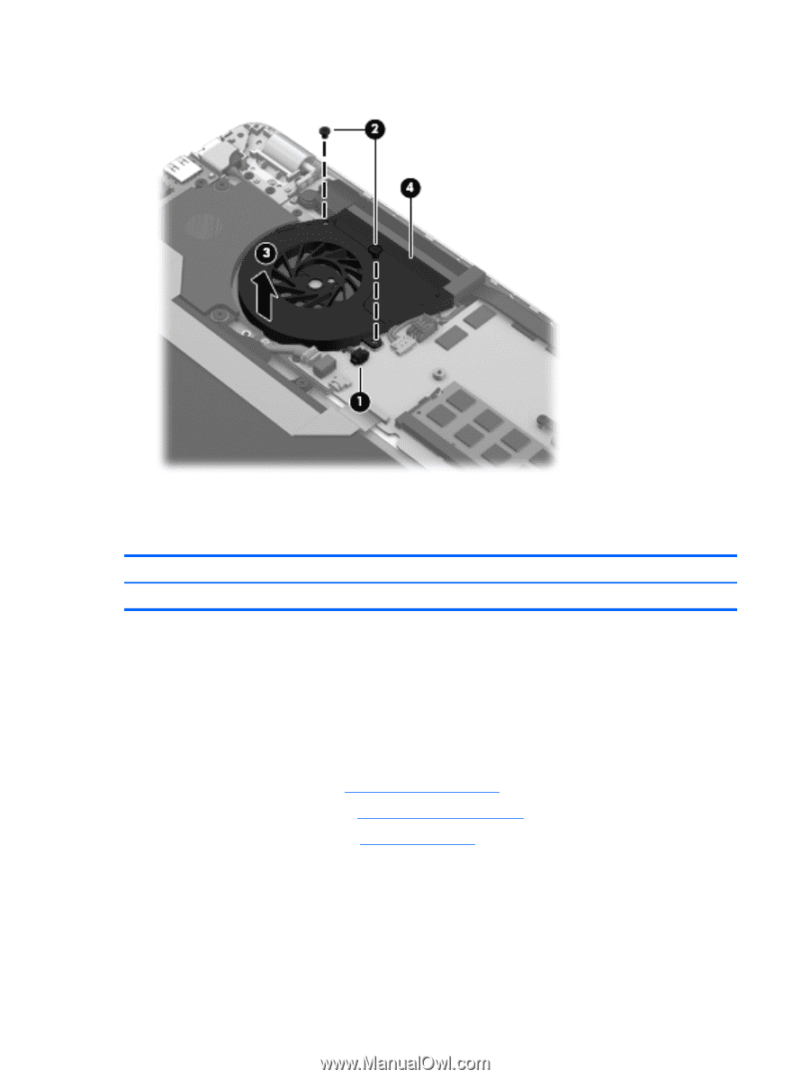
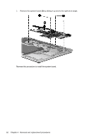
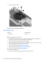
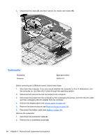
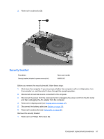
4. Remove the fan/heat sink (4). Reverse this procedure to install the fan/heat sink.. RJ-45 module cover Description RJ-45 module cover Spare part number 691642-001 Before removing the RJ-45 module cover: 1. Shut down the computer. If you are unsure whether the computer is off or in Hibernation, turn the computer on, and then shut it down through the operating system. 2. Disconnect all external devices connected to the computer. 3. Disconnect the power from the computer by first unplugging the power cord from the AC outlet and then unplugging the AC adapter from the computer. 4. Remove the display panel (see Display panel on page 32). 5. Remove the base enclosure (see Base enclosure on page 34). 6. Disconnect the battery cable (see Battery on page 36). Remove the RJ-45 module cover: 1. Remove the 2 Phillips PM screws securing the RJ-45 module cover (1). 54 Chapter 4 Removal and replacement procedures
-
 1
1 -
2
-
3
-
4
-
5
-
6
-
7
-
8
-
9
-
10
-
11
-
12
-
13
-
14
-
15
-
16
-
17
-
18
-
19
-
20
-
21
-
22
-
23
-
24
-
25
-
26
-
27
-
28
-
29
-
30
-
31
-
32
-
33
-
34
-
35
-
36
-
37
-
38
-
39
-
40
-
41
-
42
-
43
-
44
-
45
-
46
-
47
-
48
-
49
-
50
-
51
-
52
-
53
-
54
-
55
-
56
-
 57
57 -
 58
58 -
 59
59 -
 60
60 -
 61
61 -
 62
62 -
 63
63 -
 64
64 -
 65
65 -
 66
66 -
 67
67 -
68
-
69
-
70
-
71
-
72
-
73
-
74
-
75
-
76
-
77
-
78
-
79
-
80
-
81
-
82
-
83
-
84
-
85
-
86
-
87
-
88
-
89
-
90
-
91
-
92
-
93
-
94
-
95
-
96
-
97
-
98
 |
 |