HP ENVY Ultrabook CTO 6t-1000 HP Envy 6 Maintenance and Service Guide - Page 61
Fan-Heat sink
 |
View all HP ENVY Ultrabook CTO 6t-1000 manuals
Add to My Manuals
Save this manual to your list of manuals |
Page 61 highlights
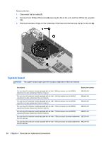
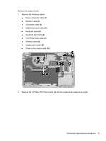
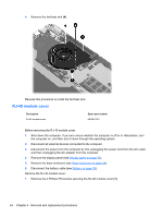
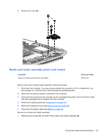
Fan-Heat sink Description Fan - Heat sink Fan - Heat sink Fan - Heat sink Fan - Heat sink Spare part number 686578-001 686579-001 691656-001 691557-001 NOTE: To properly ventilate the computer, allow at least 7.6 cm (3 in) of clearance on the left side of the computer. The computer uses an electric fan for ventilation. The fan is controlled by a temperature sensor and is designed to turn on automatically when high temperature conditions exist. These conditions are affected by high external temperatures, system power consumption, power management/battery conservation configurations, battery fast charging, and software requirements. Exhaust air is displaced through the ventilation grill located on the left side of the computer. Before removing the fan, follow these steps: 1. Shut down the computer. If you are unsure whether the computer is off or in Hibernation, turn the computer on, and then shut it down through the operating system. 2. Disconnect all external devices connected to the computer. 3. Disconnect the power from the computer by first unplugging the power cord from the AC outlet and then unplugging the AC adapter from the computer. 4. Remove the display panel (see Display panel on page 32). 5. Remove the base enclosure (see Base enclosure on page 34). 6. Disconnect the battery cable (see Battery on page 36), Remove the fan: 1. Turn the computer, with the front toward you. 2. Disconnect the fan cable (1) from the system board. 3. Remove the 4 Phillips PM 2.0×3.0 screws securing the heat sink (2), and the 2 Phillips PM 2.0×3.0 screws securing the fan (3). Component replacement procedures 53
-
 1
1 -
2
-
3
-
4
-
5
-
6
-
7
-
8
-
9
-
10
-
11
-
12
-
13
-
14
-
15
-
16
-
17
-
18
-
19
-
20
-
21
-
22
-
23
-
24
-
25
-
26
-
27
-
28
-
29
-
30
-
31
-
32
-
33
-
34
-
35
-
36
-
37
-
38
-
39
-
40
-
41
-
42
-
43
-
44
-
45
-
46
-
47
-
48
-
49
-
50
-
51
-
52
-
53
-
54
-
55
-
 56
56 -
 57
57 -
 58
58 -
 59
59 -
 60
60 -
 61
61 -
 62
62 -
 63
63 -
 64
64 -
 65
65 -
 66
66 -
67
-
68
-
69
-
70
-
71
-
72
-
73
-
74
-
75
-
76
-
77
-
78
-
79
-
80
-
81
-
82
-
83
-
84
-
85
-
86
-
87
-
88
-
89
-
90
-
91
-
92
-
93
-
94
-
95
-
96
-
97
-
98
 |
 |