HP ENVY Ultrabook CTO 6t-1000 HP Envy 6 Maintenance and Service Guide - Page 58
Remove the USB/Audio and cable see USB/Audio., USB/Audio see USB/Audio
 |
View all HP ENVY Ultrabook CTO 6t-1000 manuals
Add to My Manuals
Save this manual to your list of manuals |
Page 58 highlights
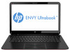
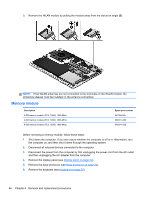
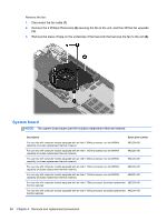
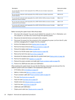
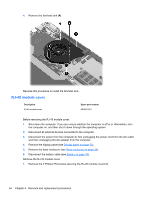
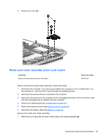
Description For use only with computer models equipped with an AMD processor (includes replacement thermal material) For use only with computer models equipped with an AMD processor (includes replacement thermal material) For use only with computer models equipped with an AMD 2.8GHz/2.0GHz processor (includes replacement thermal material) For use only with computer models equipped with an AMD 2.8GHz/2.0GHz processor (includes replacement thermal material) For use only with computer models equipped with an AMD 2.8GHz/2.0GHz processor (includes replacement thermal material) Spare part number 694436-501 694436-601 694437-001 694437-501 694437-601 Before removing the system board, follow these steps: 1. Shut down the computer. If you are unsure whether the computer is off or in Hibernation, turn the computer on, and then shut it down through the operating system. 2. Disconnect all external devices connected to the computer. 3. Disconnect the power from the computer by first unplugging the power cord from the AC outlet and then unplugging the AC adapter from the computer. 4. Remove the display panel (see Display panel on page 32). 5. Remove the base enclosure (see Base enclosure on page 34). 6. Remove the battery (see Battery on page 36). 7. Remove the WLAN module (see WLAN module on page 45). 8. Remove the hard drive (see Hard drive on page 38). 9. Disconnect the display panel cable from the system board (see Display panel on page 32). 10. Remove the speaker (see Speakers on page 60). 11. Remove the power connector and cable (see Power connector cable on page 59). 12. Remove the USB/Audio and cable (see USB/Audio). When replacing the system board, be sure that the following components are removed from the defective system board and installed on the replacement system board: ● RTC battery (see RTC battery on page 41) ● Memory module (see Memory module on page 46) ● Power connector cable (see Power connector cable on page 59) ● Fan (see Fan-Heat sink on page 53) ● Heat sink (see Fan-Heat sink on page 53) ● WLAN module see (WLAN module on page 45). ● Hard drive (see Hard drive on page 38). ● USB/Audio (see USB/Audio) ● Display panel cable (see Display panel on page 32). 50 Chapter 4 Removal and replacement procedures
-
 1
1 -
2
-
3
-
4
-
5
-
6
-
7
-
8
-
9
-
10
-
11
-
12
-
13
-
14
-
15
-
16
-
17
-
18
-
19
-
20
-
21
-
22
-
23
-
24
-
25
-
26
-
27
-
28
-
29
-
30
-
31
-
32
-
33
-
34
-
35
-
36
-
37
-
38
-
39
-
40
-
41
-
42
-
43
-
44
-
45
-
46
-
47
-
48
-
49
-
50
-
51
-
52
-
 53
53 -
 54
54 -
 55
55 -
 56
56 -
 57
57 -
 58
58 -
 59
59 -
 60
60 -
 61
61 -
 62
62 -
 63
63 -
64
-
65
-
66
-
67
-
68
-
69
-
70
-
71
-
72
-
73
-
74
-
75
-
76
-
77
-
78
-
79
-
80
-
81
-
82
-
83
-
84
-
85
-
86
-
87
-
88
-
89
-
90
-
91
-
92
-
93
-
94
-
95
-
96
-
97
-
98
 |
 |