HP Integrity rx1600 Operation and Maintenance - HP Integrity rx1600 - Page 166
Removing and Replacing the Optional Management Processor Card
 |
View all HP Integrity rx1600 manuals
Add to My Manuals
Save this manual to your list of manuals |
Page 166 highlights
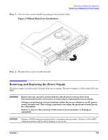
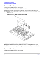
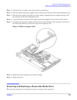
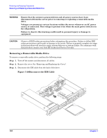
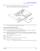
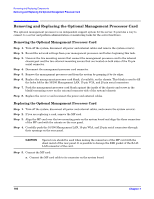
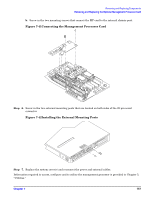
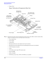
Removing and Replacing Components Removing and Replacing the Optional Management Processor Card Removing and Replacing the Optional Management Processor Card The optional management processor is an independent support system for the server. It provides a way to connect to a server and perform administration or monitoring tasks for the server hardware. Removing the Optional Management Processor Card Step 1. Turn off the system, disconnect all power and external cables and remove the system cover(s). Step 2. Record the network settings from your management processor card before beginning this task. Step 3. Unscrew the two mounting screws that connect the management processor card to the internal chassis post and the two external mounting screws that are located on both sides of the 25-pin serial connector. Step 4. Disconnect the management processor card connector. Step 5. Remove the management processor card from the system by grasping it by its edges. Step 6. Replace the management processor card blank, if available, on the chassis. This blank is used to fill the holes left by the 10/100 Management LAN, 15-pin VGA, and 25-pin serial connectors. Step 7. Push the management processor card blank against the inside of the chassis and screw in the blank's mounting screw on the external connector side of the system's chassis. Step 8. Replace the cover (s) and reconnect the power and external cables. Replacing the Optional Management Processor Card Step 1. Turn off the system, disconnect all power and external cables, and remove the system cover(s). Step 2. If you are replacing a card, remove the MP card. Step 3. Align the MP card over the two mounting posts on the system board and align the three connectors of the MP card with the cutouts on the rear panel. Step 4. Carefully push the 10/100 Management LAN, 15-pin VGA, and 25-pin serial connectors through their openings on the rear panel. CAUTION Special care should be used when mating the connectors of the MP card with the sheet metal of the rear panel. It is possible to damage the EMI gasket of the RJ-45 LAN connector of the card. Step 5. Connect the MP card: a. Connect the MP card cable to its connector on the system board. 166 Chapter 7
-
 1
1 -
2
-
3
-
4
-
5
-
6
-
7
-
8
-
9
-
10
-
11
-
12
-
13
-
14
-
15
-
16
-
17
-
18
-
19
-
20
-
21
-
22
-
23
-
24
-
25
-
26
-
27
-
28
-
29
-
30
-
31
-
32
-
33
-
34
-
35
-
36
-
37
-
38
-
39
-
40
-
41
-
42
-
43
-
44
-
45
-
46
-
47
-
48
-
49
-
50
-
51
-
52
-
53
-
54
-
55
-
56
-
57
-
58
-
59
-
60
-
61
-
62
-
63
-
64
-
65
-
66
-
67
-
68
-
69
-
70
-
71
-
72
-
73
-
74
-
75
-
76
-
77
-
78
-
79
-
80
-
81
-
82
-
83
-
84
-
85
-
86
-
87
-
88
-
89
-
90
-
91
-
92
-
93
-
94
-
95
-
96
-
97
-
98
-
99
-
100
-
101
-
102
-
103
-
104
-
105
-
106
-
107
-
108
-
109
-
110
-
111
-
112
-
113
-
114
-
115
-
116
-
117
-
118
-
119
-
120
-
121
-
122
-
123
-
124
-
125
-
126
-
127
-
128
-
129
-
130
-
131
-
132
-
133
-
134
-
135
-
136
-
137
-
138
-
139
-
140
-
141
-
142
-
143
-
144
-
145
-
146
-
147
-
148
-
149
-
150
-
151
-
152
-
153
-
154
-
155
-
156
-
157
-
158
-
159
-
160
-
 161
161 -
 162
162 -
 163
163 -
 164
164 -
 165
165 -
 166
166 -
 167
167 -
 168
168 -
 169
169 -
 170
170 -
 171
171 -
172
-
173
-
174
-
175
-
176
-
177
-
178
-
179
-
180
-
181
-
182
-
183
-
184
-
185
-
186
-
187
-
188
-
189
-
190
-
191
-
192
-
193
-
194
-
195
-
196
-
197
-
198
-
199
-
200
-
201
-
202
-
203
-
204
 |
 |