HP Integrity rx1600 Operation and Maintenance - HP Integrity rx1600 - Page 48
Installing the External Mounting Posts, Step 10.
 |
View all HP Integrity rx1600 manuals
Add to My Manuals
Save this manual to your list of manuals |
Page 48 highlights
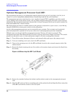
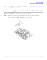
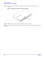
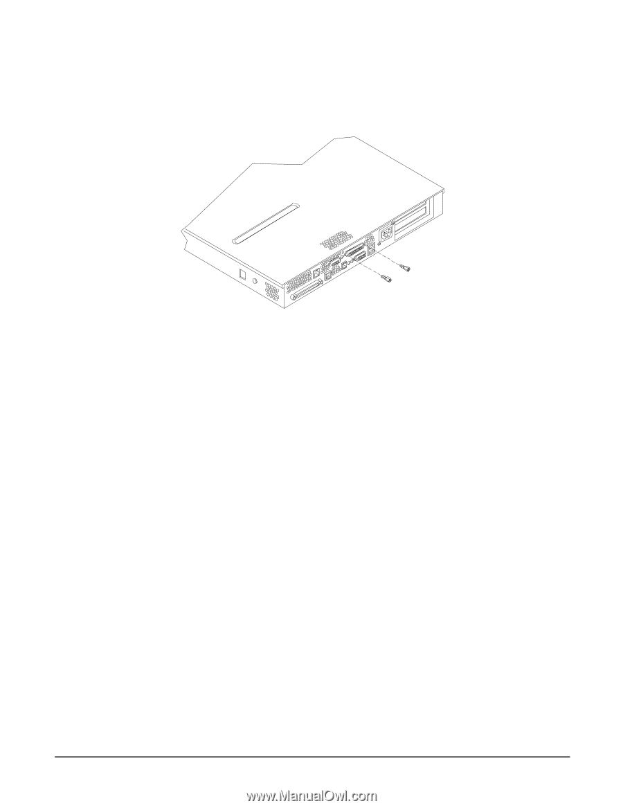
Installing and Configuring Optional Management Processor Card (MP) Step 10. Screw in the two external mounting posts that are located on both sides of the 25-pin serial connector. Figure 4-23Installing the External Mounting Posts Step 11. Replace the system cover and reconnect the power and external cables. Information required to access, configure and to utilize the management processor is provided in Chapter 5, "Utilities.". 48 Chapter 4
-
 1
1 -
2
-
3
-
4
-
5
-
6
-
7
-
8
-
9
-
10
-
11
-
12
-
13
-
14
-
15
-
16
-
17
-
18
-
19
-
20
-
21
-
22
-
23
-
24
-
25
-
26
-
27
-
28
-
29
-
30
-
31
-
32
-
33
-
34
-
35
-
36
-
37
-
38
-
39
-
40
-
41
-
42
-
 43
43 -
 44
44 -
 45
45 -
 46
46 -
 47
47 -
 48
48 -
 49
49 -
 50
50 -
 51
51 -
 52
52 -
 53
53 -
54
-
55
-
56
-
57
-
58
-
59
-
60
-
61
-
62
-
63
-
64
-
65
-
66
-
67
-
68
-
69
-
70
-
71
-
72
-
73
-
74
-
75
-
76
-
77
-
78
-
79
-
80
-
81
-
82
-
83
-
84
-
85
-
86
-
87
-
88
-
89
-
90
-
91
-
92
-
93
-
94
-
95
-
96
-
97
-
98
-
99
-
100
-
101
-
102
-
103
-
104
-
105
-
106
-
107
-
108
-
109
-
110
-
111
-
112
-
113
-
114
-
115
-
116
-
117
-
118
-
119
-
120
-
121
-
122
-
123
-
124
-
125
-
126
-
127
-
128
-
129
-
130
-
131
-
132
-
133
-
134
-
135
-
136
-
137
-
138
-
139
-
140
-
141
-
142
-
143
-
144
-
145
-
146
-
147
-
148
-
149
-
150
-
151
-
152
-
153
-
154
-
155
-
156
-
157
-
158
-
159
-
160
-
161
-
162
-
163
-
164
-
165
-
166
-
167
-
168
-
169
-
170
-
171
-
172
-
173
-
174
-
175
-
176
-
177
-
178
-
179
-
180
-
181
-
182
-
183
-
184
-
185
-
186
-
187
-
188
-
189
-
190
-
191
-
192
-
193
-
194
-
195
-
196
-
197
-
198
-
199
-
200
-
201
-
202
-
203
-
204
 |
 |
Chapter 4
Installing and Configuring
Optional Management Processor Card (MP)
48
Step 10.
Screw in the two external mounting posts that are located on both sides of the 25-pin serial
connector.
Figure 4-23Installing the External Mounting Posts
Step 11.
Replace the system cover and reconnect the power and external cables.
Information required to access, configure and to utilize the management processor is provided in Chapter 5,
“Utilities.”.