HP Integrity rx2800 HP Integrity rx2800 i2 2D Graphics Adapter Installation Gu - Page 11
Installation, Introduction, Unpacking, Installation Procedure - i2 specifications
 |
View all HP Integrity rx2800 manuals
Add to My Manuals
Save this manual to your list of manuals |
Page 11 highlights
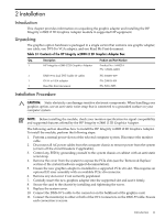
2 Installation Introduction This chapter provides information on unpacking the graphic adapter and installing the HP Integrity rx2800 i2 2D Graphics Adapter module in supported HP equipment. Unpacking The graphics option hardware is packaged in a single carton that contains one graphic adapter, one cable, one DVI-I to VGA adapter, and one Read Me First document. Table 2-1 Contents of the HP Integrity rx2800 i2 2D Graphics Adapter Box Qty. Description Product and Part Number 1 HP Integrity rx2800 i2 2D Graphics Adapter Product No.: AH423A PN: AH423-60001 1 DMS-59 to dual DVI-I cable (Y-cable) 1 DVI-I to VGA adapter 1 Read Me First document PN: 338285-009 PN: 209815-001 PN: 5991-5955 Installation Procedure CAUTION: Static electricity can damage sensitive electronic components. When handling your graphics option, use an anti-static wrist strap that is connected to a grounded surface on your computer system. NOTE: Before installing the module, check your monitor specification for signal compatibility and supported features offered by the HP Integrity rx2800 i2 2D Graphics Adapter. The following section describes how to install the HP Integrity rx2800 i2 2D Graphics Adapter. To install the module, perform the following steps: 1. Perform a normal power-down of the selected computer system. Disconnect the monitor cable. 2. Disconnect all AC power cables from the computer chassis to remove power from the system (or turn off the circuit breakers if applicable). 3. Control any ESD by grounding yourself to the system chassis or cabinet with an anti-static wrist strap. 4. Remove the cover from the system to expose the PCIe slots (see the 'Remove & Replace' section of the system hardware support documentation). 5. Ensure the new graphics adapter is installed in a supported PCIe x16 slot. This requires an optional I/O riser assembly with an available PCIe x16 connector. 6. Remove any slot cover if not currently populated. 7. Carefully insert the new graphics adapter into the supported slot and seat it firmly. 8. Secure the card to the chassis by installing and tightening the screw. 9. Replace the system cover. 10. Connect the DMS-59 Y-cable to the connector on the bulkhead of the graphics card. 11. Connect the monitor(s) to either or both of the DVI-I connectors on the DMS-59 cable. Ensure each connection is secure. Introduction 11
-
 1
1 -
2
-
3
-
4
-
5
-
 6
6 -
 7
7 -
 8
8 -
 9
9 -
 10
10 -
 11
11 -
 12
12 -
 13
13 -
 14
14 -
 15
15 -
 16
16 -
17
-
18
-
19
 |
 |