HP LH4r HP Netserver LP 1000r User Guide, Chapter 13 Update - Page 6
Attaching Outer-Rails to the Rack, Location Marks on the Rack's Columns
 |
View all HP LH4r manuals
Add to My Manuals
Save this manual to your list of manuals |
Page 6 highlights
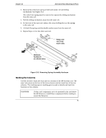
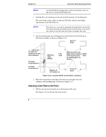
Chapter 13 Alternative Rack Mounting (4-Post) NOTE Use the HP Rack Configuration Tools to determine where in the rack to mount the HP Netserver. 1. Find the EIA unit markings on the rack and the location for the Netserver. The screw holes cover a span of only one EIA unit, which is the height requirement of the HP Netserver. NOTE The Netserver can only be mounted into both holes of one EIA Unit, but cannot be mounted across two EIA units. You cannot use a hole in one EIA unit and a hole in another EIA unit. 2. Use the masking tape (or marking pen) to mark above the 3rd hole up on both front columns, as shown in Figure 13-3. Rear of Rack represents the EIA unit numbers on the rack columns. 3rd Hole From Bottom 1st Hole From Bottom Masking Tape Marker Left Side Mark this face and edge of the columns Right with masking tape Side or marking pen, as shown. Bottom of HP NetServer Front of Rack Figure 13-3. Location Marks on the Rack's Columns 3. Mark the forward face and edge of the left-rear and right-rear rack columns, with masking tape, as shown in Figure 13-3. Attaching Outer-Rails to the Rack 1. Pull the anti-tip foot forward out of the bottom of the rack. See Figure 13-4 for the anti-tip foot location. 6
-
 1
1 -
 2
2 -
 3
3 -
 4
4 -
 5
5 -
 6
6 -
 7
7 -
 8
8 -
 9
9 -
 10
10 -
 11
11 -
 12
12 -
13
 |
 |
