HP LH4r HP Netserver LP 1000r User Guide, Chapter 13 Update - Page 7
Leveler, Screws 4, Anti-tip Foot, Extended, Mounting Outer-Rails to Columns
 |
View all HP LH4r manuals
Add to My Manuals
Save this manual to your list of manuals |
Page 7 highlights
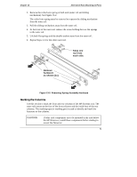
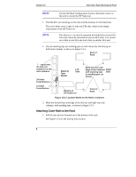
Chapter 13 Alternative Rack Mounting (4-Post) 2. Lower the leveler screws on the rack's lower four corners to make firm contact with the floor. See Figure 13-4. 3. Align the left outer-rail assembly to the left front and rear columns as shown in Figure 13-4. 4. Insert the front outer-rail pins into the column holes (1st & 3rd) just below the marking tape on the front column. See Figure 13-3. The front mounting pins of the outer-rail should go into the front face of the front column. Leveler Screws (4) Anti-tip Foot Extended Figure 13-4. Mounting Outer-Rails to Columns 5. Insert the last screw stud on the outer rail into the center hole of the three holes in the EIA unit just below the marking tape on the rear column. See Figure 13-4. 6. Repeat Steps 3 through 5 for the outer-rail assembly on the right front and rear columns. 7
-
 1
1 -
 2
2 -
 3
3 -
 4
4 -
 5
5 -
 6
6 -
 7
7 -
 8
8 -
 9
9 -
 10
10 -
 11
11 -
 12
12 -
13
 |
 |
