HP LJ476UT User Manual
HP LJ476UT Manual
 |
View all HP LJ476UT manuals
Add to My Manuals
Save this manual to your list of manuals |
HP LJ476UT manual content summary:
- HP LJ476UT | User Manual - Page 1
HP ProBook 4530s Notebook PC HP ProBook 4730s Notebook PC Maintenance and Service Guide - HP LJ476UT | User Manual - Page 2
to change without notice. The only warranties for HP products and services are set forth in the express warranty statements accompanying such products and services. Nothing herein should be construed as constituting an additional warranty. HP shall not be liable for technical or editorial errors - HP LJ476UT | User Manual - Page 3
Safety warning notice WARNING! To reduce the possibility of heat-related injuries or of overheating the computer, do not place the computer directly on your lap or obstruct the computer air vents. Use the computer only on a hard, flat surface. Do not allow another hard surface, such as an adjoining - HP LJ476UT | User Manual - Page 4
iv Safety warning notice - HP LJ476UT | User Manual - Page 5
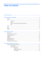
and fingerprint reader (select models only 11 Keys ...13 Front ...14 Left ...15 Right ...16 Bottom ...17 3 Illustrated parts catalog ...18 Service tag ...18 Computer major components ...19 Display components ...27 Plastics Kit ...29 Cable Kit ...30 Mass storage devices ...30 Miscellaneous parts - HP LJ476UT | User Manual - Page 6
44 Equipment guidelines 45 Component replacement procedures 46 Service tag ...46 Battery ...47 SIM ...48 Bottom door ...49 Optical RJ-11 jack cable ...84 System board ...85 Hard drive extension board (4730s models 89 RTC battery ...91 Fan ...93 Heat sink ...95 Processor ...97 Power cable ...100 - HP LJ476UT | User Manual - Page 7
DVD (purchased separately) ......... 132 8 Power cord set requirements ...134 Requirements for all countries and regions 134 Requirements for specific countries and regions 135 9 Recycling ...136 Battery ...136 Display ...136 Index ...142 vii - HP LJ476UT | User Manual - Page 8
viii - HP LJ476UT | User Manual - Page 9
1 Product description Category Product Name Processors Chipset Graphics Description HP ProBook 4530s Notebook PC HP ProBook 4730s Notebook PC Intel® Core™ i7 processor, Quad Core 2630QM, 2.00-GHz (Turbo up to 2.90) processor 6-MB L3 cache, 8 threads Intel Core i7 processor, Dual Core 2620M, 2. - HP LJ476UT | User Manual - Page 10
(4096 × 1) ● 3072 (2048 + 1024) ● 2048 (2048 × 1) ● 2048 (1024 × 2) ● 1024 (1024 × 1) Supports 7-mm/9.5-mm/12.7-mm, 2.5-in SATA hard drives with HP DriveGuard Customer-accessible 4530s (UMA) √ √ √ 4530s (Disc) √ √ √ √ √ √ √ √ √ √ 4730s (Disc) √ √ √ √ 2 Chapter 1 Product description - HP LJ476UT | User Manual - Page 11
options by way of wireless module: Two WLAN antennas built into display assembly Supports "no WLAN" option 4530s (UMA) √ 4530s (Disc) √ 4730s (Disc) √ √ √ √ √ √ √ √ √ √ √ √ √ √ √ √ √ √ √ √ √ √ √ √ √ √ √ √ √ √ √ √ √ √ √ √ √ √ √ √ √ √ √ √ √ √ √ √ √ 3 - HP LJ476UT | User Manual - Page 12
(SIM) security (customer- √ accessible in battery bay) Supports "no WWAN" option √ Supports the following WWAN modules: √ ● Qualcomm Gobi port √ √ Full-sized keyboard with numeric keypad √ √ 4730s (Disc) √ Touchpad includes: supports 2-way scroll with legend, taps √ √ √ enabled - HP LJ476UT | User Manual - Page 13
battery L-shape 9-cell, 93-Wh Li-ion battery 6-cell, 55-Wh Li-ion battery 6-cell, 47-Wh Li-ion battery Integrated fingerprint reader Intel AT support Support Kensington security lock Support Microsoft Office 2010 Starter EDGI 4530s (UMA) √ 4530s (Disc) √ 4730s (Disc) √ √ √ √ √ √ √ √ √ √ - HP LJ476UT | User Manual - Page 14
Vista Basic 32 with Microsoft Office 2010 √ Professional Windows 7 Starter with Office 2010 Starter √ Windows 7 Starter with Office 2010 Starter - EDGI √ Restore Media: 4530s (Disc) √ √ 4730s (Disc) √ √ 6 Chapter 1 Product description - HP LJ476UT | User Manual - Page 15
Service only Web-only support: Windows XP Professional Certified: Microsoft WHQL End-user replaceable parts: AC adapter Battery (system) Hard drive Memory module Optical drive WLAN module WWAN module, SIM Keyboard 4530s (UMA) 4530s (Disc) 4730s (Disc) √ √ - HP LJ476UT | User Manual - Page 16
2 External component identification Display Component (1) Speakers (2) (2) Internal display switch (3) WWAN antennas (2)* (select models only) (4) WLAN antennas (2)* (5) Internal microphone(s) (1 or 2 depending on model) (6) Webcam light (select models only) Description Produce sound. - HP LJ476UT | User Manual - Page 17
of the Regulatory, Safety, and Environmental Notices that applies to your country or region. These notices are located in Help and Support. Top TouchPad Component (1) (2) TouchPad on/off button TouchPad (3) Left TouchPad button (4) Right TouchPad button Description Turns the TouchPad on and - HP LJ476UT | User Manual - Page 18
. ● On: The computer is on. ● Off: The computer is off or in Hibernation. NOTE: For more information, refer to "HP QuickWeb" in this guide and to the HP QuickWeb software Help. ● White: An integrated wireless device, such as a wireless local area network (WLAN) device and/or a Bluetooth® device - HP LJ476UT | User Manual - Page 19
: ● Windows 7-Select Start > Control Panel > System and Security > Power Options. ● Windows Vista-Select Start > Control Panel > System and Maintenance > Power Options ● Or refer to the HP Notebook Reference Guide. Top 11 - HP LJ476UT | User Manual - Page 20
QuickWeb, press the button to open the default Web browser. NOTE: For more information, refer to "HP QuickWeb" in this guide and to the HP QuickWeb software Help. If your computer does not have HP QuickWeb software, the button does not perform any action or function. Turns the wireless feature on or - HP LJ476UT | User Manual - Page 21
Keys Component (1) esc key (2) Function keys (3) num lk key (4) Integrated numeric keypad (5) fn key (6) Start key (7) Menu key Description Displays system information when pressed in combination with the fn key. Execute frequently used system functions when pressed in combination - HP LJ476UT | User Manual - Page 22
Audio-in (microphone) jack Description ● White: The hard drive or optical drive is being accessed. ● Amber: HP 3D DriveGuard has temporarily parked the hard drive. Supports the following digital card formats: ● Memory Stick Pro ● Memory Stick Duo Pro ● MultiMediaCard ● MultiMediaCard Micro ● Secure - HP LJ476UT | User Manual - Page 23
in the computer are fully charged. If the computer is not plugged into an external power source, the light stays off until the battery reaches a low battery level. Connects an AC adapter. Enables airflow to cool internal components. NOTE: The computer fan starts up automatically to cool internal - HP LJ476UT | User Manual - Page 24
Component (8) (9) ExpressCard slot USB port (10) USB port Right Description Reads and writes to ExpressCards. Connects an optional USB device. Connects an optional USB device. Component (1) USB ports (2) Description Connect optional USB devices. (2) RJ-11 (modem) jack (select models only) - HP LJ476UT | User Manual - Page 25
identity module (SIM) model 4530s only). The SIM slot is located inside the battery bay. Enable airflow to cool internal components. NOTE: The computer fan starts up automatically the module to restore computer functionality, and then contact technical support through Help and Support. Bottom 17 - HP LJ476UT | User Manual - Page 26
product. ● Part number/Product number (p/n) (3). This number provides specific information about the product's hardware components. The part number helps a service technician to determine what components and parts are needed. ● Warranty period (4). This number describes the duration (in years) of - HP LJ476UT | User Manual - Page 27
Computer major components Computer major components 19 - HP LJ476UT | User Manual - Page 28
and WWAN ● 39.6-cm (15.6-inch) HD+, anti-glare, without webcam ● 39.6-cm (15.6-inch) HD+, anti-glare, with webcam For use in silver HP ProBook 4730s models: ● 43.9-cm (17.3-inch), HD+, anti-glare, without webcam ● 43.9-cm (17.3-inch), HD+, anti-glare, with webcam Keyboard (includes cable) NOTE: For - HP LJ476UT | User Manual - Page 29
number 646303-001 for 4530s models, 646304-001 for 4730s models. See Cable Kit on page 30 for more Cable Kit spare part number information. Lid switch board For use in HP ProBook 4530s models: 646289-001 For use in HP ProBook 4730s models: 646290-001 Speaker assembly (includes housing) For - HP LJ476UT | User Manual - Page 30
-001 Intel Celeron processor, Dual Core B810, 1.6-GHz, with 2-MB L3 cache (includes thermal grease) 646760-001 WWAN modules HP lc2010 HSPA Mobile Broadband Module 632155-001 HP un2430 EV-DO/HSPA Mobile Broadband Module 634400-001 WLAN module Atheros AR9002WB-1NGB 802.11b/g/n 1x1 WiFi and - HP LJ476UT | User Manual - Page 31
Item Description Spare part number Realtek 8188BC8 802.11a/b/g/n 2x2 WiFi and Bluetooth 3.0+HS Combo Adapter for use in Afghanistan, Albania, Algeria, Andorra, Angola, Antigua and Barbuda, Argentina, Armenia, Aruba, Australia, Austria, Azerbaijan, Bahamas, Bahrain, Baltics, Bangladesh, Barbados, - HP LJ476UT | User Manual - Page 32
Item Description Spare part number Ralink 8190BC8 802.11b/g/n 2x2 WiFi and Bluetooth 3.0+HS Combo Adapter for use in Afghanistan, Albania, Algeria, Andorra, Angola, Antigua and Barbuda, Argentina, Armenia, Aruba, Australia, Austria, Azerbaijan, Bahamas, Bahrain, Baltics, Bangladesh, Barbados, - HP LJ476UT | User Manual - Page 33
extension board 646291-001 USB board For use in 4530s models 646287-001 For use in 4730s models 646288-001 Base enclosure For use in 4530s models 646261-001 For use in 4730s models 646262-001 Battery, Li-ion 9-cell (93 WHr, 2.8 Ah), for use only in 4530s models 633809-001 8-cell (73 - HP LJ476UT | User Manual - Page 34
DVD±RW and CD-RW SuperMulti DL Combo Drive ● DVD-ROM Drive For use in 4730s models: ● Blu-ray BD-R/RE DVD±RW SuperMulti DL Drive ● Blu-ray ROM DVD± ● DVD-ROM Drive Bottom door For use in 4530s models For use in 4730s models Spare part number 621569-001 621565-001 639736-001 633252-001 603785-001 - HP LJ476UT | User Manual - Page 35
components Item Description (1) Display bezel For use with HP ProBook 4530s models with a webcam For use with HP ProBook 4530s models without a webcam For use with HP ProBook 4730s models with a webcam For use with HP ProBook 4730s models without a webcam (2) Display hinge covers Spare part - HP LJ476UT | User Manual - Page 36
cm (15.6-inch) HD+ 43.9-cm (17.3-inch) HD+, anti-glare (5) Display hinges (includes left and right hinges) For use with HP ProBook 4530s models For use with HP ProBook 4730s models (6) Webcam cable (7) Display Cable Kit For use in models without a webcam For use in 4530s models with HD+ displays For - HP LJ476UT | User Manual - Page 37
Plastics Kit Item Description Plastics Kit for use in 4530s models Plastics Kit for use in 4730s models (1) RJ-11 protective insert (2) Secure Digital card protective insert (3) ExpressCard slot protective insert (4) Optical drive protective insert Spare part number 646309-001 646310-001 - HP LJ476UT | User Manual - Page 38
Kit for use in 4530s models Cable Kit for use in 4730s models (1) Battery connector cable (2) Power connector cable (3) RJ-11 connector cable ● DVD±RW and CD-RW SuperMulti DL Combo Drive ● DVD-ROM Drive For use in 4730s models: ● Blu-ray BD-R/RE DVD±RW SuperMulti DL Drive ● Blu-ray Disc ROM with - HP LJ476UT | User Manual - Page 39
the United Kingdom For use in the United States Rubber Kit (includes SIM bumper and feet) For use with model 4530s For use with model 4730s Screw Kit Spare part number 635225-001 622641-001 647944-001 Spare part number 609939-001 609948-001 609940-001 609947-001 490371-D01 490371 - HP LJ476UT | User Manual - Page 40
model 4730s Sequential part number listing Spare part number 449137-001 490371-001 490371-011 490371-021 490371-031 490371-061 490371-081 490371-111 490371-201 490371-202 490371-291 490371-AA1 490371-AB1 490371-AD1 490371-AR1 490371-BB1 490371-D01 490371-D61 Description RTC battery Power cord - HP LJ476UT | User Manual - Page 41
Spare part number 593127-001 602993-001 603785-001 605766-001 609939-001 609940-001 609947-001 609948-001 621565-001 621569-001 Description Atheros AR9002WB-1NGB 802.11b/g/n 1x1 WiFi and Bluetooth 2.1+EDR Combo Adapter for use in Afghanistan, Albania, Algeria, Andorra, Angola, Antigua and Barbuda, - HP LJ476UT | User Manual - Page 42
include a modem module cable. The modem module cable is included in the Cable Kit, spare part number 646303-001 for 4530s models, 646304-001 for 4730s models. See Cable Kit on page 30 for more Cable Kit spare part number information. Ralink 5390GN 802.11b/g/n 1x1 WiFi Adapter for use in - HP LJ476UT | User Manual - Page 43
, 7200-rpm hard drive 6-cell, 47 WHr, 2.2 Ah Li-ion battery, for use only in 4530s models 8-cell, 73 WHr, 2.8 Ah Li-ion battery, for use only in 4730s models 9-cell, 93 WHr, 2.8 Ah Li-ion battery, for use only in 4530s models HP un2430 EV-DO/HSPA Mobile Broadband Module 500-GB, 5400-rpm - HP LJ476UT | User Manual - Page 44
models with a webcam Display bezel for use with HP ProBook 4730s models without a webcam Display bezel for use with HP ProBook 4730s models with a webcam Display enclosure for use in HP ProBook 4530s models Display enclosure for use in HP ProBook 4730s models Display Cable Kit for use in 4530s HD - HP LJ476UT | User Manual - Page 45
models WWAN antennas Display hinges for use on 4530s models (includes left and right hinges) Display hinges for use on 4730s models (includes left and right hinges) Display hinge covers for use in 4530s models Display hinge covers for use in 4530s models Heat sink for - HP LJ476UT | User Manual - Page 46
for more Cable Kit spare part information) 646304-001 Cable Kit for use in 4730s models (see Cable Kit on page 30 for more Cable Kit spare part information for use in 4530s models 646306-001 Screw Kit for use in 4730s models 646307-001 Rubber Kit for use with model 4530s (includes SIM bumper and - HP LJ476UT | User Manual - Page 47
models (includes bracket, bezel, and screws) Blu-ray ROM DVD±RW SuperMulti DL Drive for use in 4730s models (includes bracket, bezel, and screws) 6-cell, 55 WHr, 2.8 Ah battery for use only in 4530s models Intel Pentium B940 processor , 2.0-GHz, with 2-MB L3 cache (include thermal material) Intel - HP LJ476UT | User Manual - Page 48
Spare part number 658340-001 658341-001 658342-001 658343-001 658344-001 658345-001 Description System board for use in 4530s models with UMA graphics with WWAN and USB 2.0 in all countries and regions except for Russia and the People's Republic of China System board for use in 4530s models with - HP LJ476UT | User Manual - Page 49
Flat-bladed screwdriver ● Phillips P0 and P1 screwdrivers ● Torx T8 screwdriver Service considerations The following sections include some of the considerations that you must keep in Apply pressure only at the points designated in the maintenance instructions. Preliminary replacement requirements 41 - HP LJ476UT | User Manual - Page 50
Cables and connectors CAUTION: When servicing the computer, be sure that cables are placed in their proper locations during the reassembly process. Improper cable placement can damage the computer. Cables must - HP LJ476UT | User Manual - Page 51
Grounding guidelines Electrostatic discharge damage Electronic components are sensitive to electrostatic discharge (ESD). Circuitry design and structure determine the degree of sensitivity. Networks built into many integrated circuits provide some protection, but in many cases, ESD contains enough - HP LJ476UT | User Manual - Page 52
material. ● Use a wrist strap connected to a properly grounded work surface and use properly grounded tools and equipment. ● Use conductive field service tools, such as cutters, screwdrivers, and vacuums. ● When fixtures must directly contact dissipative surfaces, use fixtures made only of static - HP LJ476UT | User Manual - Page 53
with ground cords of one megohm resistance ● Static-dissipative tables or floor mats with hard ties to the ground ● Field service kits ● Static awareness labels ● Material-handling packages ● Nonconductive plastic bags, tubes, or boxes ● Metal tote boxes ● Electrostatic voltage levels and - HP LJ476UT | User Manual - Page 54
product. ● Part number/Product number (p/n) (3). This number provides specific information about the product's hardware components. The part number helps a service technician to determine what components and parts are needed. ● Warranty period (4). This number describes the duration (in years) of - HP LJ476UT | User Manual - Page 55
use only in 4530s models 8-cell, 73 WHr, 2.8 Ah Li-ion battery, for use only in 4730s models 6-cell, 55 WHr, 2.8 Ah, for use only in 4530s models 6-cell, 47 WHr, 2.2 Ah Li-ion battery, for use only in 4530s models Spare part number 633809-001 633807-001 650938-001 633805-001 Before - HP LJ476UT | User Manual - Page 56
power cord from the AC outlet, and then unplugging the AC adapter from the computer. 4. Remove the battery (see Battery on page 47). Remove the SIM: 1. Position the computer upside-down with the battery bay toward you. 2. Press in on the SIM (1). (The module is partially ejected from the SIM slot - HP LJ476UT | User Manual - Page 57
door for use in 4530s models Bottom door for use in 4730s models Spare part number 646263-001 646264-001 Before disassembling the then unplugging the AC adapter from the computer. 4. Remove the battery (see Battery on page 47). Remove the bottom door: 1. Position the computer upside-down on a - HP LJ476UT | User Manual - Page 58
RW and CD-RW SuperMulti DL Combo Drive DVD-ROM Drive For use in 4730s models: Blu-ray BD-R/RE DVD±RW SuperMulti DL Drive Blu-ray ROM AC outlet, and then unplugging the AC adapter from the computer. 4. Remove the battery (see Battery on page 47). 5. Remove the bottom door (see Bottom door on page 49 - HP LJ476UT | User Manual - Page 59
4. Remove the optical drive (3) from the computer. 5. If it is necessary to replace the optical drive bracket, position the optical drive with the rear toward you. 6. Remove the two Phillips PM2.0×3.0 screws (1) that secure the optical drive bracket to the optical drive. 7. Remove the optical drive - HP LJ476UT | User Manual - Page 60
from the computer by first unplugging the power cord from the AC outlet, and then unplugging the AC adapter from the computer. 4. Remove the battery (see Battery on page 47). 5. Remove the bottom door (see Bottom door on page 49). Remove the hard drive: 1. Position the computer upside-down with the - HP LJ476UT | User Manual - Page 61
4. Remove the hard drive (3) from the hard drive bay. 5. If it is necessary to replace the hard drive bracket, remove the tape (1) that secures the Mylar cover down onto the bracket, and then lift to open the Mylar cover (2). 6. Remove the two Phillips PM3.0×3.0 hard drive bracket screws (3) from - HP LJ476UT | User Manual - Page 62
from the computer by first unplugging the power cord from the AC outlet, and then unplugging the AC adapter from the computer. 4. Remove the battery (see Battery on page 47). 5. Remove the bottom door (see Bottom door on page 49). Remove the memory module: 1. Position the computer upside-down with - HP LJ476UT | User Manual - Page 63
3. Remove the memory module (2) by pulling the module away from the slot at an angle. NOTE: Memory modules are designed with a notch (3) to prevent incorrect insertion into the memory module slot. NOTE: The computer uses two memory sockets. The top socket houses the expansion memory module and is - HP LJ476UT | User Manual - Page 64
the WLAN module are not interchangeable. Description HP lc2010 HSPA Mobile Broadband Module HP un2430 EV-DO/HSPA Mobile Broadband Module Spare AC outlet, and then unplugging the AC adapter from the computer. 4. Remove the battery (see Battery on page 47). 5. Remove the SIM (see SIM on page 48). 6. - HP LJ476UT | User Manual - Page 65
4. Remove the WWAN module (3) by pulling the module away from the slot at an angle. NOTE: WWAN modules are designed with a notch (4) to prevent incorrect insertion. Figure 4-1 Removing the WWAN module NOTE: If the WWAN antennas are not connected to the terminals on the WWAN module, the protective - HP LJ476UT | User Manual - Page 66
WLAN/Bluetooth combo card The computer uses a card that provides both WLAN and Bluetooth functionality. CAUTION: The WLAN module and the WWAN module are not interchangeable. Description Spare part number Atheros AR9002WB-1NGB 802.11b/g/n 1x1 WiFi and Bluetooth 2.1+EDR Combo Adapter for use in - HP LJ476UT | User Manual - Page 67
Description Spare part number Ralink 5390GN 802.11b/g/n 1x1 WiFi Adapter for use in Afghanistan, Albania, Algeria, Andorra, Angola, Antigua and Barbuda, Argentina, Armenia, Aruba, Australia, Austria, Azerbaijan, Bahamas, Bahrain, Baltics, Bangladesh, Barbados, Belarus, Belgium, Belize, Benin, - HP LJ476UT | User Manual - Page 68
Description Spare part number Realtek 8188GN 802.11b/g/n 1x1 WiFi Adapter for use in Afghanistan, Albania, Algeria, Andorra, Angola, Antigua and Barbuda, Argentina, Armenia, Aruba, Australia, Austria, Azerbaijan, Bahamas, Bahrain, Baltics, Bangladesh, Barbados, Belarus, Belgium, Belize, Benin, - HP LJ476UT | User Manual - Page 69
from the computer by first unplugging the power cord from the AC outlet, and then unplugging the AC adapter from the computer. 4. Remove the battery (see Battery on page 47). 5. Remove the bottom door (see Bottom door on page 49). Remove the WLAN module: 1. Position the computer upside-down with the - HP LJ476UT | User Manual - Page 70
4. Remove the WLAN module (3) by pulling the module away from the slot at an angle. NOTE: WLAN modules are designed with a notch (4) to prevent incorrect insertion. NOTE: If the WLAN antennas are not connected to the terminals on the WLAN module, the protective sleeves must be installed on the - HP LJ476UT | User Manual - Page 71
from the computer by first unplugging the power cord from the AC outlet, and then unplugging the AC adapter from the computer. 4. Remove the battery (see Battery on page 47). 5. Remove the bottom door (see Bottom door on page 49). Remove the keyboard: 1. Position the computer upside-down with the - HP LJ476UT | User Manual - Page 72
4. Insert a screwdriver or similar tool into the gap near the WWAN module compartment and push to disengage the keyboard. 5. Position the computer upright with the front toward you. 6. Open the computer as far as possible. 7. Lift and rotate the keyboard (1) until it rests on the palm rest (2). NOTE - HP LJ476UT | User Manual - Page 73
reader and with USB 3.0 With a fingerprint reader and USB 2.0 Without a fingerprint reader and with USB 2.0 Top cover for use in model 4730s: With a fingerprint reader Without a fingerprint reader Spare part number 646251-001 646253-001 658344-001 658345-001 646257-001 646260-001 Before removing - HP LJ476UT | User Manual - Page 74
4. Remove the battery (see Battery on page 47). 5. Remove the following components: a. Bottom door (see Bottom door on page covers (2) 10 Torx T8M2.5×6.0 screws NOTE: The following image shows model 4530s. Model 4730s has 15 Torx screws on the bottom. 66 Chapter 4 Removal and replacement procedures - HP LJ476UT | User Manual - Page 75
: (1) 3 Phillips PM2.0×4.0 screws from the optical drive bay (2) 3 Phillips PM2.5×2.5 broadhead screws from the battery bay NOTE: The following image shows model 4530s. Model 4730s has 5 screws in the battery bay 4. Turn the computer upright and open it as far as possible. 5. Remove the 6 Torx T8M2 - HP LJ476UT | User Manual - Page 76
7. Position the computer on its side with the display open. 8. Insert a screwdriver through the holes in the battery bay and press to disengage the top cover from the computer. 9. Position the computer upright with the front toward you. 68 Chapter 4 Removal and replacement procedures - HP LJ476UT | User Manual - Page 77
10. To remove the top cover, pull up on the top of the top cover (1), pull upward on the left (2) and right sides (3), and then lift the bottom of the top cover (4) to remove it enough to access the card reader cable underneath. 11. Lift the front of the top cover slightly to gain access to the - HP LJ476UT | User Manual - Page 78
use in 4530s models Card reader board for use in 4730s models Spare part number 646292-001 646293-001 Before removing the AC outlet, and then unplugging the AC adapter from the computer. 4. Remove the battery (see Battery on page 47). 5. Remove the following components: a. Bottom door (see Bottom - HP LJ476UT | User Manual - Page 79
4530s models (includes housing) Speaker assembly for use in 4730s models (includes housing) Spare part number 646298-001 646299-001 outlet, and then unplugging the AC adapter from the computer. 4. Remove the battery (see Battery on page 47). 5. Remove the following components: a. Bottom door (see - HP LJ476UT | User Manual - Page 80
NOTE: The following image shows model 4530s. Speaker appearance differs in model 4730s. 1. Position the top cover upside-down with the front toward you. 2. If disassembling model 4530s, remove the power button board cable from atop the left - HP LJ476UT | User Manual - Page 81
use in 4530s models Quick Launch board for use in 4730s models Spare part number 646296-001 646297-001 Before removing the AC outlet, and then unplugging the AC adapter from the computer. 4. Remove the battery (see Battery on page 47). 5. Remove the following components: a. Bottom door (see Bottom - HP LJ476UT | User Manual - Page 82
for use in model 4530s Power button board for use in model 4730s Spare part number 646294-001 646295-001 Before removing the power button , and then unplugging the AC adapter from the computer. 4. Remove the battery (see Battery on page 47). 5. Remove the following components: a. Bottom door (see - HP LJ476UT | User Manual - Page 83
NOTE: Model 4530s shown below. Power button board appearance differs in model 4730s. 1. Position the top cover upside-down with the front toward you. 2. Remove the Phillips PM2.0×4.0 screw (1) that secures the board to the top cover. 3. Lift - HP LJ476UT | User Manual - Page 84
Kit, spare part number 646303-001 for 4530s models, 646304-001 for 4730s models. See Cable Kit on page 30 for more Cable Kit spare part outlet, and then unplugging the AC adapter from the computer. 4. Remove the battery (see Battery on page 47). 5. Remove the following components: a. Bottom door (see - HP LJ476UT | User Manual - Page 85
4. Disconnect the modem module cable (3) from the modem module. Reverse this procedure to install the modem module. Component replacement procedures 77 - HP LJ476UT | User Manual - Page 86
for use in 4530s models Lid switch for use in 4730s models Spare part number 646289-001 646290-001 Before removing the AC outlet, and then unplugging the AC adapter from the computer. 4. Remove the battery (see Battery on page 47). 5. Remove the following components: a. Bottom door (see Bottom door - HP LJ476UT | User Manual - Page 87
4. Lift the board from the computer (4). Reverse this procedure to install the lid switch. Component replacement procedures 79 - HP LJ476UT | User Manual - Page 88
for use in 4530s models USB board for use in 4730s models Spare part number 646287-001 646288-001 Before removing the AC outlet, and then unplugging the AC adapter from the computer. 4. Remove the battery (see Battery on page 47). 5. Remove the following components: a. Bottom door (see Bottom door - HP LJ476UT | User Manual - Page 89
5. Lift the board and cable straight up out of the computer (5) Reverse this procedure to install the USB board. Component replacement procedures 81 - HP LJ476UT | User Manual - Page 90
the computer by first unplugging the power cord from the AC outlet, and then unplugging the AC adapter from the computer. 4. Remove the battery (see Battery on page 47). 5. Remove the following components: a. Bottom door (see Bottom door on page 49). b. Optical drive (see Optical drive on page 50 - HP LJ476UT | User Manual - Page 91
3. Lift the optical drive connector from the computer (2). Reverse this procedure to install the optical drive connector. Component replacement procedures 83 - HP LJ476UT | User Manual - Page 92
Kit, spare part number 646303-001 for 4530s models, 646304-001 for 4730s models. Before removing the RJ-11 jack cable, follow these steps: 1. and then unplugging the AC adapter from the computer. 4. Remove the battery (see Battery on page 47). 5. Remove the following components: a. Bottom door (see - HP LJ476UT | User Manual - Page 93
4. Remove the RJ-11 jack from the clip built into the base enclosure (3). Reverse this procedure to install the RJ-11 jack cable. System board NOTE: All system board spare part kits include replacement thermal material. Description System board for use in all countries and regions except for - HP LJ476UT | User Manual - Page 94
from the computer by first unplugging the power cord from the AC outlet, and then unplugging the AC adapter from the computer. 4. Remove the battery (see Battery on page 47). 5. Remove the following components: a. Bottom door (see Bottom door on page 49). b. Hard drive (see Hard drive on page 52 - HP LJ476UT | User Manual - Page 95
(1) and the display cable (2) from the system board, and remove the cables from the routing clip (3). 3. If removing the system board from model 4730s, skip to step 6. If removing the system board from model 4530s, remove the two Phillips PM2.5×5.0 screws (1) that secure the system board to the - HP LJ476UT | User Manual - Page 96
6. If removing the system board from model 4730s, remove the three Torx T8M2.0×5.0 screws (1) that gain access to the cables underneath (6). 9. On the bottom of the system board, disconnect the battery connector cable (1) from the system board. 10. Disconnect the smaller power cable (2) and the - HP LJ476UT | User Manual - Page 97
Hard drive extension board (4730s models) Description Hard drive extension board Spare part cord from the AC outlet, and then unplugging the AC adapter from the computer. 4. Remove the battery (see Battery on page 47). 5. Remove the following components: a. Bottom door (see Bottom door on page - HP LJ476UT | User Manual - Page 98
2. Pull the hard drive extension board straight off the system board. Reverse this procedure to install the hard drive extension board. 90 Chapter 4 Removal and replacement procedures - HP LJ476UT | User Manual - Page 99
from the computer by first unplugging the power cord from the AC outlet, and then unplugging the AC adapter from the computer. 4. Remove the battery (see Battery on page 47). 5. Remove the following components: a. Bottom door (see Bottom door on page 49). b. Hard drive (see Hard drive on page 52 - HP LJ476UT | User Manual - Page 100
3. Lift the battery from the system board (2). Reverse this procedure to install the RTC battery. 92 Chapter 4 Removal and replacement procedures - HP LJ476UT | User Manual - Page 101
from the computer by first unplugging the power cord from the AC outlet, and then unplugging the AC adapter from the computer. 4. Remove the battery (see Battery on page 47). 5. Remove the following components: a. Bottom door (see Bottom door on page 49). b. Hard drive (see Hard drive on page 52 - HP LJ476UT | User Manual - Page 102
high temperature conditions exist. These conditions are affected by high external temperatures, system power consumption, power management/battery conservation configurations, battery fast charging, and software requirements. Exhaust air is displaced through the ventilation grill located on the left - HP LJ476UT | User Manual - Page 103
from the computer by first unplugging the power cord from the AC outlet, and then unplugging the AC adapter from the computer. 4. Remove the battery (see Battery on page 47). 5. Remove the following components: a. Bottom door (see Bottom door on page 49). b. Hard drive (see Hard drive on page 52 - HP LJ476UT | User Manual - Page 104
3. Remove the heat sink from the system board (7). 4. To remove the UMA heat sink, in the order indicated, loosen the four captive Phillips screws (1) - (4) that secure the heat sink to the system board. 5. Remove the heat sink from the system board (5). NOTE: For discrete models, thoroughly clean - HP LJ476UT | User Manual - Page 105
NOTE: For UMA models, thoroughly clean thermal material from the surface of the system board (1) and heat sink (2) each time you remove the heat sink. All heat sink and processor spare part kits include thermal material. Reverse this procedure to install the heat sink. Processor NOTE: All processor - HP LJ476UT | User Manual - Page 106
from the computer by first unplugging the power cord from the AC outlet, and then unplugging the AC adapter from the computer. 4. Remove the battery (see Battery on page 47). 5. Remove the following components: a. Bottom door (see Bottom door on page 49). b. Hard drive (see Hard drive on page 52 - HP LJ476UT | User Manual - Page 107
Remove the processor: 1. Position the computer upside-down with the front toward you. 2. Use a flat-bladed screwdriver to turn the processor locking screw (1) one-half turn counterclockwise until you hear a click. 3. Lift the processor (2) straight up and remove it. NOTE: The gold triangle (3) on - HP LJ476UT | User Manual - Page 108
spare part number 646303-001 for 4530s models, 646304-001 for 4730s models. Before removing the power cable, follow these steps: 1. outlet, and then unplugging the AC adapter from the computer. 4. Remove the battery (see Battery on page 47). 5. Remove the following components: a. Bottom door (see - HP LJ476UT | User Manual - Page 109
3. Lift the power cable assembly from the computer (2). Reverse this procedure to install the power cable. Component replacement procedures 101 - HP LJ476UT | User Manual - Page 110
39.6-cm (15.6-inch) HD+, anti-glare, with webcam For use in silver HP ProBook 4730s models: ● 43.9-cm (17.3-inch), HD+, anti-glare, without webcam ● 43 then unplugging the AC adapter from the computer. 4. Remove the battery (see Battery on page 47). 5. Remove the following components: a. Bottom door - HP LJ476UT | User Manual - Page 111
3. If necessary, disconnect the webcam cable (1) and display cable (2) from the system board, and then remove the cables from the clip (3). Component replacement procedures 103 - HP LJ476UT | User Manual - Page 112
4. Remove the four Phillips PM2.5×7.0 screws (1) from the hinges, and then remove the display from the computer (2). When installing the display assembly, be sure that the wireless antenna cables are routed and arranged properly. Failure to properly route the antennas can result in degradation of - HP LJ476UT | User Manual - Page 113
and off the display to remove them. Display hinge covers are available using spare part number 646281-001 for 4530s models and 646282-001 for 4730s models. 6. To replace the display bezel, remove the two rubber screw covers (1) and the two Torx T8M2.5×6.0 screws (2) in the bottom corners of the - HP LJ476UT | User Manual - Page 114
bezel is available using the following spare part numbers: 646265-001: 4530s models without a webcam 646266-001: 4530s models with a webcam 646267-001: 4730s models without a webcam 646268-001: 4730s models with a webcam 8. Remove the display bezel. 106 Chapter 4 Removal and replacement procedures - HP LJ476UT | User Manual - Page 115
9. If it is necessary to replace the webcam module (shown in the following image) or microphone module from the display enclosure, disconnect the cable from the module (1), and then gently pull the module away from the double-sided tape on the display enclosure (2). The webcam module is available - HP LJ476UT | User Manual - Page 116
(2). The display cable is available using spare part number 605766-001 for models without a webcam, 646273-001 for 4530s HD+ models, 646274-001 for 4730s models. 13. If it is necessary to replace the display hinges, remove the four Phillips PM2.5×3.0 screws (1) that secure each display hinge to the - HP LJ476UT | User Manual - Page 117
available using spare part number 646279-001 for 4530s models and 646280-001 for 4730s models. 15. If you need to remove the WLAN or WWAN antennas, using spare part number 646276-001 for 4530s models, 646277-001 for 4730s models, and the WWAN antennas are available using spare part number 646278- - HP LJ476UT | User Manual - Page 118
display cable is available using spare part number 605766-001 for models without a webcam, 646273-001 for 4530s HD+ models, 646274-001 for 4730s models. The webcam cable is available using spare part number 646275-001. Reverse this procedure to reassemble and install the display assembly. Note the - HP LJ476UT | User Manual - Page 119
Component replacement procedures 111 - HP LJ476UT | User Manual - Page 120
to a USB port can be used with Computer Setup only if USB legacy support is enabled. To start Computer Setup, follow these steps: 1. Turn on the main Computer Setup screen, press esc, and then follow the on-screen instructions. NOTE: You can use either a pointing device (TouchPad, pointing stick, or - HP LJ476UT | User Manual - Page 121
icon in the lower-left corner of the screen, and then follow the on-screen instructions. - or - Use the tab key and the arrow keys to select File > icon in the lower-left corner of the screen, and then follow the on-screen instructions. - or - Use the tab key and the arrow keys to select File > - HP LJ476UT | User Manual - Page 122
HP Web site. Most BIOS updates on the HP Web site are packaged in compressed files called SoftPaqs. Some download packages contain a file named Readme.txt, which contains information regarding installing and troubleshooting Help and Support > Maintain. 2. Follow the on-screen instructions to identify - HP LJ476UT | User Manual - Page 123
following the on-screen instructions. NOTE: After a up test and checks for intermittent problems that the start-up test does Battery test-This test analyzes the condition of the battery. If the battery fails the test, contact HP Customer Support to report the issue and purchase a replacement battery - HP LJ476UT | User Manual - Page 124
models Length Width Height (front to rear) Weight (equipped with optical drive, 1 DIMM, hard drive, optical drive, WLAN module, 6 cell battery) Dimensions, 4730s models Length Width Height (front to rear) Weight (equipped with optical drive, 1 DIMM, hard drive, optical drive, WLAN module, 6 cell - HP LJ476UT | User Manual - Page 125
Metric U.S. Operating 125 g, 2 ms, half-sine Nonoperating 200 g, 2 ms, half-sine Random vibration Operating 0.75 g zero-to-peak, 10 Hz to 500 Hz, 0.25 oct/min sweep rate Nonoperating 1.50 g zero-to-peak, 10 Hz to 500 Hz, 0.5 oct/min sweep rate NOTE: Applicable product safety standards - HP LJ476UT | User Manual - Page 126
PPI Surface treatment Contrast ratio Response time Brightness Viewing angle Backlight Luminance uniformity @ 13 points Lifetime (1/2 luminance) Color coordinate (white) Color tolerance (White) Color tolerance (R, G, B) Color gamut Metric U.S. 100 Anti-glare or BrightView 300:1 (typical) - Anti- - HP LJ476UT | User Manual - Page 127
43.9-cm (17.3-in), HD+ display specifications Active diagonal size Resolution Active area PPI Surface treatment Contrast ratio Response time Brightness Viewing angle Backlight Luminance uniformity @ 13 points Lifetime (1/2 luminance) Color coordinate (white) Color tolerance (White) Color tolerance - HP LJ476UT | User Manual - Page 128
referring to hard drive storage capacity. Actual accessible capacity is less. Actual drive specifications may differ slightly. NOTE: Certain restrictions and exclusions apply. Contact technical support for details. 120 Chapter 6 Specifications - HP LJ476UT | User Manual - Page 129
Blu-ray BD-R/RE DVD±RW SuperMulti DL Drive specifications Applicable disc Access time Random Maximum Media Capacity (read) Maximum Media Capacity (write) Data transfer rate 24X CD-ROM 8X DVD 2X BD-ROM 16X CD-R 16X CD-RW 8X DVD+R 6X DVD+RW 8X DVD-R 6X DVD-RW 4X DVD+R Dual Layer 4X DVD-R Dual Layer - HP LJ476UT | User Manual - Page 130
DVD±RW and CD-RW SuperMulti DL Combo Drive specifications Applicable disc Center hole diameter Disc diameter Standard disc Mini disc Disc thickness Track pitch Access time Random Full stroke Audio output level Cache buffer Data transfer rate 24X CD-ROM 8X DVD-ROM 24X CD-R 16X CD-RW 8X DVD+R 4X DVD+ - HP LJ476UT | User Manual - Page 131
Blu-ray Disc ROM with SuperMulti DVD±R/RW DL Drive Applicable disc Access time Random Cache buffer Data transfer rate 24X CD-ROM 8X DVD 24X CD-R 16X CD-RW 8X DVD+R 4X DVD+RW 8X DVD-R 4X DVD-RW 2.4X DVD+R(9) 5X DVD-RAM 1X BD-ROM 1X BD-R read 1X BD-RE read Transfer mode Read: Write: CD-DA, CD - HP LJ476UT | User Manual - Page 132
DVD-ROM Drive specifications Applicable disc Center hole diameter Disc diameter Standard disc Mini disc Disc thickness Track pitch Access time Random Full stroke Audio output level Cache buffer Data transfer rate CD-R (24X) CD-RW (10X) CD-ROM (24X) DVD (8X) Multiword DMA mode 2 Startup time Stop - HP LJ476UT | User Manual - Page 133
be prompted for your permission or password for tasks such as installing software, running utilities, or changing Windows settings. Refer to Windows Help and Support for more information. After you open Device Manager, drill-down to a device and double-click it to access its properties. To access - HP LJ476UT | User Manual - Page 134
● Restoring the computer to a previous state ● Recovering information using recovery tools NOTE: For detailed instructions, perform a search for these topics in Help and Support. In case of system instability, HP recommends that you print the recovery procedures and save them for later use. NOTE - HP LJ476UT | User Manual - Page 135
: DVDs and DVDs with double-layer (DL) support store more information than CDs, so using them for Backup and Restore. 2. Follow the on-screen instructions to set up your backup, create a system image also use Windows Startup Repair to fix problems that might prevent Windows from starting correctly. - HP LJ476UT | User Manual - Page 136
then click Disk Management. NOTE: If the Windows partition and the HP Recovery partition are not listed, you must recover your operating system and instructions. NOTE: For additional information on recovering information using the Windows tools, perform a search for these topics in Help and Support - HP LJ476UT | User Manual - Page 137
separately) To order a Windows 7 operating system DVD, go to http://www.hp.com/support, select your country or region, and follow the on-screen instructions. You can also order the DVD by calling technical support. For contact information, refer to the Worldwide Telephone Numbers booklet included - HP LJ476UT | User Manual - Page 138
Restoring the computer to a previous state ● Recovering information using recovery tools NOTE: For detailed instructions, perform a search for these topics in Help and Support. NOTE: In case of system instability, HP recommends that you print the recovery procedures and save them for later use. NOTE - HP LJ476UT | User Manual - Page 139
and Restore Center. 2. Follow the on-screen instructions to back up your entire computer (select use Windows Startup Repair to fix problems that might prevent Windows from starting HP Recovery partition. To find the partitions, select Start > Computer. NOTE: If the Windows partition and the HP - HP LJ476UT | User Manual - Page 140
) To order a Windows Vista operating system DVD, go to http://www.hp.com/support, select your country or region, and follow the on-screen instructions. You can also order the DVD by calling technical support. For contact information, refer to the Worldwide Telephone Numbers booklet included with - HP LJ476UT | User Manual - Page 141
Windows Vista operating system DVD into the optical drive before the Windows operating system loads. 3. When prompted, press any keyboard key. 4. Follow the on-screen instructions. 5. Click Next. 6. Select Repair your computer. 7. Follow the on-screen - HP LJ476UT | User Manual - Page 142
8 Power cord set requirements The wide range input feature of the computer permits it to operate from any line voltage from 100 to 120 volts AC, or from 220 to 240 volts AC. The 3-conductor power cord set included with the computer meets the requirements for use in the country or region where the - HP LJ476UT | User Manual - Page 143
Requirements for specific countries and regions Country/region Accredited agency Applicable note number Australia EANSW 1 Austria OVE 1 Belgium CEBC 1 Canada CSA 2 Denmark DEMKO 1 Finland FIMKO 1 France UTE 1 Germany VDE 1 Italy IMQ 1 Japan METI 3 The Netherlands - HP LJ476UT | User Manual - Page 144
battery in general household waste. Follow the local laws and regulations in your area for computer battery them carefully. NOTE: Materials Disposal. This HP product contains mercury in the backlight in .eiae.org. This section provides disassembly instructions for the display assembly. The display - HP LJ476UT | User Manual - Page 145
Perform the following steps to disassemble the display assembly: 1. Remove all screw covers (1) and screws (2) that secure the display bezel to the display assembly. 2. Lift up and out on the left and right inside edges (1) and the top and bottom inside edges (2) of the display bezel until the bezel - HP LJ476UT | User Manual - Page 146
4. Disconnect all display panel cables (1) from the display inverter and remove the inverter (2). 5. Remove all screws (1) that secure the display panel assembly to the display enclosure. 6. Remove the display panel assembly (2) from the display enclosure. 7. Position the display panel assembly - HP LJ476UT | User Manual - Page 147
10. Remove the display panel frame (2) from the display panel. 11. Remove the screws (1) that secure the backlight cover to the display panel. 12. Lift the top edge of the backlight cover (2) and swing it outward. 13. Remove the backlight cover. 14. Position the display panel right-side up. Display - HP LJ476UT | User Manual - Page 148
15. Remove the backlight cables (1) from the clip (2) in the display panel. 16. Position the display panel upside-down. WARNING! The backlight contains mercury. Exercise caution when removing and handling the backlight to avoid damaging this component and causing exposure to the mercury. 17. Remove - HP LJ476UT | User Manual - Page 149
18. Remove the backlight from the backlight frame. 19. Disconnect the display panel cable (1) from the LCD panel. 20. Remove the screws (2) that secure the LCD panel to the display rear panel. 21. Release the LCD panel (3) from the display rear panel. 22. Release the tape (4) that secures the LCD - HP LJ476UT | User Manual - Page 150
number 25, 36 battery removal 47 spare part number 25, 47 battery bay 17 battery connector cable, illustrated 30 battery release latches 17 BIOS 12 C Cable Kit contents 30 spare part number 30, 38 cables, service considerations 42 caps lock light, identifying 10 card reader board removal 70 spare - HP LJ476UT | User Manual - Page 151
spare part numbers 20, 37, 63 keypad, integrated numeric 13 keys esc 13 fn 13 function 13 menu 13 num lk 13 start 13 L legacy support, USB 112 lid switch removal 78 spare part number 37, 78 lid switch board spare part number 21 lights AC adapter 15 caps lock 10 - HP LJ476UT | User Manual - Page 152
-11 jack cable removal 84 RJ-45 (network) jack, identifying 15 RTC battery removal 91 spare part number 25, 32, 91 Rubber Kit, spare part product description 5 service considerations 41 service tag 18, 46 serviceability, product description USB legacy support 112 USB port, identifying 16 144 Index - HP LJ476UT | User Manual - Page 153
USB ports, identifying 16 V vents, identifying 15, 17 W webcam 9 product description 3 spare part number 28, 36 webcam light, identifying 8 webcam, identifying 9 Windows 7 operating system DVD 129 Windows Backup and Restore 126 Windows Vista operating system DVD 132 wireless antennas disconnecting
-
 1
1 -
 2
2 -
 3
3 -
 4
4 -
 5
5 -
 6
6 -
 7
7 -
8
-
9
-
10
-
11
-
12
-
13
-
14
-
15
-
16
-
17
-
18
-
19
-
20
-
21
-
22
-
23
-
24
-
25
-
26
-
27
-
28
-
29
-
30
-
31
-
32
-
33
-
34
-
35
-
36
-
37
-
38
-
39
-
40
-
41
-
42
-
43
-
44
-
45
-
46
-
47
-
48
-
49
-
50
-
51
-
52
-
53
-
54
-
55
-
56
-
57
-
58
-
59
-
60
-
61
-
62
-
63
-
64
-
65
-
66
-
67
-
68
-
69
-
70
-
71
-
72
-
73
-
74
-
75
-
76
-
77
-
78
-
79
-
80
-
81
-
82
-
83
-
84
-
85
-
86
-
87
-
88
-
89
-
90
-
91
-
92
-
93
-
94
-
95
-
96
-
97
-
98
-
99
-
100
-
101
-
102
-
103
-
104
-
105
-
106
-
107
-
108
-
109
-
110
-
111
-
112
-
113
-
114
-
115
-
116
-
117
-
118
-
119
-
120
-
121
-
122
-
123
-
124
-
125
-
126
-
127
-
128
-
129
-
130
-
131
-
132
-
133
-
134
-
135
-
136
-
137
-
138
-
139
-
140
-
141
-
142
-
143
-
144
-
145
-
146
-
147
-
148
-
149
-
150
-
151
-
152
-
153
 |
 |

HP ProBook 4530s Notebook PC
HP ProBook 4730s Notebook PC
Maintenance and Service Guide