HP LJ476UT User Manual - Page 115
The display panel is available using the following spare part numbers
 |
View all HP LJ476UT manuals
Add to My Manuals
Save this manual to your list of manuals |
Page 115 highlights
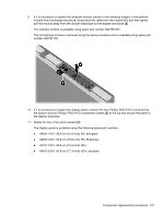
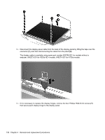
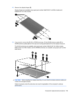
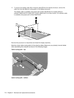
9. If it is necessary to replace the webcam module (shown in the following image) or microphone module from the display enclosure, disconnect the cable from the module (1), and then gently pull the module away from the double-sided tape on the display enclosure (2). The webcam module is available using spare part number 642795-001. The microphone module is removed using the same procedure and is available using spare part number 642797-001. 10. If it is necessary to replace the display panel, remove the four Phillips PM2.5×5.0 screws (1) at the bottom and two Phillips PM2.5×5.0 broadhead screws (2) at the top that secure the panel to the display enclosure. 11. Rotate the top of the panel upward (3). The display panel is available using the following spare part numbers: ● 646311-001: 39.6-cm (15.6-inch) HD, anti-glare ● 646312-001: 39.6-cm (15.6-inch) HD, Brightview ● 647011-001: 39.6-cm (15.6-inch) HD+ ● 646313-001: 43.9-cm (17.3-inch) HD+, anti-glare Component replacement procedures 107
-
 1
1 -
2
-
3
-
4
-
5
-
6
-
7
-
8
-
9
-
10
-
11
-
12
-
13
-
14
-
15
-
16
-
17
-
18
-
19
-
20
-
21
-
22
-
23
-
24
-
25
-
26
-
27
-
28
-
29
-
30
-
31
-
32
-
33
-
34
-
35
-
36
-
37
-
38
-
39
-
40
-
41
-
42
-
43
-
44
-
45
-
46
-
47
-
48
-
49
-
50
-
51
-
52
-
53
-
54
-
55
-
56
-
57
-
58
-
59
-
60
-
61
-
62
-
63
-
64
-
65
-
66
-
67
-
68
-
69
-
70
-
71
-
72
-
73
-
74
-
75
-
76
-
77
-
78
-
79
-
80
-
81
-
82
-
83
-
84
-
85
-
86
-
87
-
88
-
89
-
90
-
91
-
92
-
93
-
94
-
95
-
96
-
97
-
98
-
99
-
100
-
101
-
102
-
103
-
104
-
105
-
106
-
107
-
108
-
109
-
 110
110 -
 111
111 -
 112
112 -
 113
113 -
 114
114 -
 115
115 -
 116
116 -
 117
117 -
 118
118 -
 119
119 -
 120
120 -
121
-
122
-
123
-
124
-
125
-
126
-
127
-
128
-
129
-
130
-
131
-
132
-
133
-
134
-
135
-
136
-
137
-
138
-
139
-
140
-
141
-
142
-
143
-
144
-
145
-
146
-
147
-
148
-
149
-
150
-
151
-
152
-
153
 |
 |
