HP Management LAN Blade for bh7800 Site Preparation Guide, Second Edition - HP - Page 27
Cabinet Performance Grounding (High Frequency Ground), Raised Floor, absolute safety minimum.
 |
View all HP Management LAN Blade for bh7800 manuals
Add to My Manuals
Save this manual to your list of manuals |
Page 27 highlights
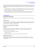
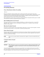
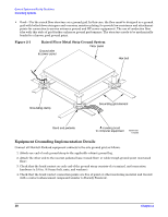
General System and Facility Guidelines Grounding Systems Cabinet Performance Grounding (High Frequency Ground) Signal interconnects between system cabinets require high frequency ground return paths. Connect all cabinets to site ground. NOTE In some cases power distribution system green (green/yellow) wire ground conductors are too long and inductive to provide adequate high frequency ground return paths. Therefore, a ground strap (customer-supplied) should be used for connecting the system cabinet to the site-grounding grid (customer-supplied). When connecting this ground, ensure that the raised floor is properly grounded for high frequency. Power panels located in close proximity to the computer equipment should also be connected to site grounding grid. Methods of providing a sufficiently high frequency ground grid are described in the next sections. Raised Floor "High Frequency Noise" Grounding If a raised floor system is used, install a complete signal-grounding grid for maintaining equal potential over a broad band of frequencies. The grounding grid should be connected to the equipment cabinet and electrical service entrance ground at multiple connection points using a minimum #6 AWG (16mm2) wire ground conductor. Figure 2-1 illustrates a metallic strip grounding system. NOTE Regardless of the grounding connection method used, the raised floor should be grounded as an absolute safety minimum. Hewlett-Packard recommends the following approaches: • Excellent-Add a grounding grid to the subfloor. The grounding grid should be made of copper strips mounted to the subfloor. The strips should be 0.032 in. (0.08 cm) thick and a minimum of 3.0 in. (8.0 cm) wide. Connect each pedestal to four strips using 1/4 in. (6.0 mm) bolts tightened to the manufacturer's torque recommendation. • Better-A grounded #6 AWG minimum copper wire grid mechanically clamped to floor pedestals and properly bonded to the building/site ground. Chapter 2 27
-
 1
1 -
2
-
3
-
4
-
5
-
6
-
7
-
8
-
9
-
10
-
11
-
12
-
13
-
14
-
15
-
16
-
17
-
18
-
19
-
20
-
21
-
 22
22 -
 23
23 -
 24
24 -
 25
25 -
 26
26 -
 27
27 -
 28
28 -
 29
29 -
 30
30 -
 31
31 -
 32
32 -
33
-
34
-
35
-
36
-
37
-
38
-
39
-
40
-
41
-
42
-
43
-
44
-
45
-
46
 |
 |