HP Management LAN Blade for bh7800 Site Preparation Guide, Second Edition - HP - Page 28
Equipment Grounding Implementation Details, Raised Floor Metal Strip Ground System
 |
View all HP Management LAN Blade for bh7800 manuals
Add to My Manuals
Save this manual to your list of manuals |
Page 28 highlights
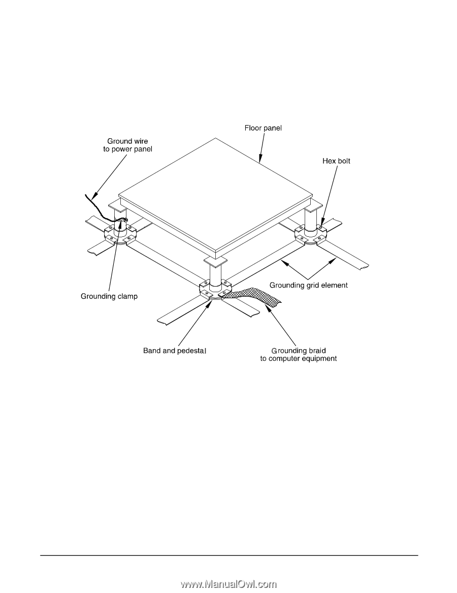
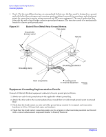
General System and Facility Guidelines Grounding Systems • Good-Use the raised floor structure as a ground grid. In this case, the floor must be designed as a ground grid with bolted down stringers and corrosion resistive plating (to provide low resistance and attachment points for connection to service entrance ground and HP server equipment). The use of conductive floor tiles with this style of grid further enhances ground performance. The structure needs to be mechanically bonded to a known good ground point. Figure 2-1 Raised Floor Metal Strip Ground System 60SP010A 11/30/99 Equipment Grounding Implementation Details Connect all Hewlett-Packard equipment cabinets to the site ground grid as follows: 1. Attach one end of each ground strap to the applicable cabinet ground lug. 2. Attach the other end to the nearest pedestal base (raised floor) or cable trough ground point (nonraised floor). 3. Check that the braid contact on each end of the ground strap consists of a terminal, and connection hardware (a 1/4-in. (6.0-mm) bolt, nuts, and washers). 4. Check that the braid contact connection points are free of paint or other insulating material and treated with a contact enhancement compound (similar to Burndy Penetrox). 28 Chapter 2
-
 1
1 -
2
-
3
-
4
-
5
-
6
-
7
-
8
-
9
-
10
-
11
-
12
-
13
-
14
-
15
-
16
-
17
-
18
-
19
-
20
-
21
-
22
-
 23
23 -
 24
24 -
 25
25 -
 26
26 -
 27
27 -
 28
28 -
 29
29 -
 30
30 -
 31
31 -
 32
32 -
 33
33 -
34
-
35
-
36
-
37
-
38
-
39
-
40
-
41
-
42
-
43
-
44
-
45
-
46
 |
 |