HP Model 715/80 hp 9000 series 700 model 715 workstations service handbook (a2 - Page 130
Processor Board
 |
View all HP Model 715/80 manuals
Add to My Manuals
Save this manual to your list of manuals |
Page 130 highlights
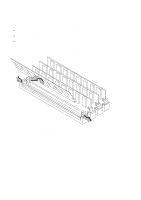
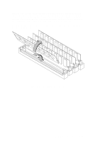
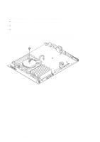
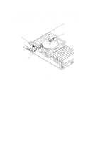
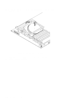
Processor Board Before removing the processor board, perform the following steps: S Remove the optional external graphics processor (if installed). S Remove the floor stand. S Open the system unit. S Remove the EISA assembly or optional graphics (CRX or HCRX) board, if present. S Disconnect all internal and external cables. When installing the processor board, use a wide, flat object, such as a wooden ruler or flat-tipped screwdriver, between the front wall of the system unit and the edge of the processor board to lever the board toward the rear of the system (see Figure 5-45). This will enable you to align the screw hole and seat the connectors at the rear of the system unit. Swap the memory boards to the new/exchange processor board, as shown in the "Memory" section. If you are replacing a 715/C, 715/33, 715/50, or 715/75 processor board with another 715/C, 715/33, 715/50, or 715/75 processor board, remove the EEPROM from the failed processor board and install it in the new/exchange processor board, as shown in the "System EEPROM" section. Field Replaceable Units 5-45
-
 1
1 -
2
-
3
-
4
-
5
-
6
-
7
-
8
-
9
-
10
-
11
-
12
-
13
-
14
-
15
-
16
-
17
-
18
-
19
-
20
-
21
-
22
-
23
-
24
-
25
-
26
-
27
-
28
-
29
-
30
-
31
-
32
-
33
-
34
-
35
-
36
-
37
-
38
-
39
-
40
-
41
-
42
-
43
-
44
-
45
-
46
-
47
-
48
-
49
-
50
-
51
-
52
-
53
-
54
-
55
-
56
-
57
-
58
-
59
-
60
-
61
-
62
-
63
-
64
-
65
-
66
-
67
-
68
-
69
-
70
-
71
-
72
-
73
-
74
-
75
-
76
-
77
-
78
-
79
-
80
-
81
-
82
-
83
-
84
-
85
-
86
-
87
-
88
-
89
-
90
-
91
-
92
-
93
-
94
-
95
-
96
-
97
-
98
-
99
-
100
-
101
-
102
-
103
-
104
-
105
-
106
-
107
-
108
-
109
-
110
-
111
-
112
-
113
-
114
-
115
-
116
-
117
-
118
-
119
-
120
-
121
-
122
-
123
-
124
-
 125
125 -
 126
126 -
 127
127 -
 128
128 -
 129
129 -
 130
130 -
 131
131 -
 132
132 -
 133
133 -
 134
134 -
 135
135 -
136
-
137
-
138
-
139
-
140
-
141
-
142
-
143
-
144
-
145
-
146
-
147
-
148
-
149
-
150
 |
 |
