HP Nc4000 HP Compaq nc4010 Notebook PC - Maintenance and Service Guide - Page 121
display assembly to the base enclosure., Lift the display assembly straight up and remove it.
 |
View all HP Nc4000 manuals
Add to My Manuals
Save this manual to your list of manuals |
Page 121 highlights
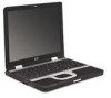
Removal and Replacement Procedures 10. Disconnect the display inverter 1 and video cables 2 from the system board. 11. Remove the two T8M2.0×8.0 screws 3 that secure the display assembly to the base enclosure. Disconnecting the Display Cables and Removing the Display Assembly Screws 12. Lift the display assembly straight up and remove it. Reverse the above procedure to install the display assembly. 5-42 Maintenance and Service Guide
-
 1
1 -
2
-
3
-
4
-
5
-
6
-
7
-
8
-
9
-
10
-
11
-
12
-
13
-
14
-
15
-
16
-
17
-
18
-
19
-
20
-
21
-
22
-
23
-
24
-
25
-
26
-
27
-
28
-
29
-
30
-
31
-
32
-
33
-
34
-
35
-
36
-
37
-
38
-
39
-
40
-
41
-
42
-
43
-
44
-
45
-
46
-
47
-
48
-
49
-
50
-
51
-
52
-
53
-
54
-
55
-
56
-
57
-
58
-
59
-
60
-
61
-
62
-
63
-
64
-
65
-
66
-
67
-
68
-
69
-
70
-
71
-
72
-
73
-
74
-
75
-
76
-
77
-
78
-
79
-
80
-
81
-
82
-
83
-
84
-
85
-
86
-
87
-
88
-
89
-
90
-
91
-
92
-
93
-
94
-
95
-
96
-
97
-
98
-
99
-
100
-
101
-
102
-
103
-
104
-
105
-
106
-
107
-
108
-
109
-
110
-
111
-
112
-
113
-
114
-
115
-
 116
116 -
 117
117 -
 118
118 -
 119
119 -
 120
120 -
 121
121 -
 122
122 -
 123
123 -
 124
124 -
 125
125 -
 126
126 -
127
-
128
-
129
-
130
-
131
-
132
-
133
-
134
-
135
-
136
-
137
-
138
-
139
-
140
-
141
-
142
-
143
-
144
-
145
-
146
-
147
-
148
-
149
-
150
-
151
-
152
-
153
-
154
-
155
-
156
-
157
-
158
-
159
-
160
-
161
-
162
-
163
-
164
-
165
-
166
-
167
-
168
-
169
-
170
-
171
-
172
-
173
-
174
-
175
-
176
-
177
-
178
-
179
-
180
-
181
-
182
-
183
-
184
-
185
-
186
-
187
-
188
-
189
 |
 |

5–42
Maintenance and Service Guide
Removal and Replacement Procedures
10. Disconnect the display inverter
1
and video cables
2
from
the system board.
11. Remove the two T8M2.0×8.0 screws
3
that secure the
display assembly to the base enclosure.
Disconnecting the Display Cables and Removing the Display
Assembly Screws
12. Lift the display assembly straight up and remove it.
Reverse the above procedure to install the display assembly.