HP Omni 10 5603cl HP Omni10 Maintenance and Service Guide - Page 25
Removal and replacement procedures, Back cover
 |
View all HP Omni 10 5603cl manuals
Add to My Manuals
Save this manual to your list of manuals |
Page 25 highlights
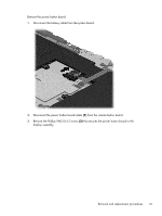
Removal and replacement procedures CAUTION: Components described in this chapter should only be accessed by an authorized service provider. Accessing these parts can damage the tablet and void the warranty. This chapter provides removal and replacement procedures for authorized service provider only parts. There are as many as 19 screws that must be removed, replaced, and/or loosened when servicing the tablet. Make special note of each screw size and location during removal and replacement. Back cover Description Spare part number Back cover (includes internal shielding) 736881-001 10.1-in, AG, LED, WUXGA, TouchScreen, display assembly 739812-001 NOTE: The display assembly does not include the display panel cable. The display panel cable is available using spare part number 739817-001. Before disassembling the tablet, follow these steps: 1. Turn off the tablet. If you are unsure whether the tablet is off or in Hibernation, turn the tablet on, and then shut it down through the operating system. 2. Disconnect the power from the tablet by unplugging the power cord from the tablet. 3. Disconnect all external devices from the tablet. Remove the back cover: CAUTION: Before turning the display assembly upside down, make sure the work surface is clear of tools, screws, and any other foreign objects. Failure to follow this caution can result in damage to the display assembly. 1. Place the tablet on a flat surface, display panel side down, with the power button toward you. CAUTION: When inserting the plastic tool into the tablet as described in Step 2, make sure not to insert the tool into the power button area. Failure to follow this caution can result in damage to the tablet. 2. Insert a thin, plastic tool (1) between the back cover and the display assembly. The first insertion point should be between the power button (2) and the middle of the top edge (3) of the back cover. 3. Separate the top edge of the back cover (4) from the display assembly. CAUTION: When removing the back cover, make sure the bottom edge, opposite the power button, is the last edge removed. Failure to follow this caution can result in damage to the tablet. Removal and replacement procedures 19
-
 1
1 -
2
-
3
-
4
-
5
-
6
-
7
-
8
-
9
-
10
-
11
-
12
-
13
-
14
-
15
-
16
-
17
-
18
-
19
-
 20
20 -
 21
21 -
 22
22 -
 23
23 -
 24
24 -
 25
25 -
 26
26 -
 27
27 -
 28
28 -
 29
29 -
 30
30 -
31
-
32
-
33
-
34
-
35
-
36
-
37
-
38
-
39
-
40
-
41
-
42
-
43
-
44
-
45
-
46
-
47
-
48
-
49
-
50
-
51
-
52
-
53
-
54
-
55
-
56
-
57
-
58
-
59
-
60
-
61
 |
 |
