HP Omni 10 5603cl HP Omni10 Maintenance and Service Guide - Page 48
The wireless antenna cable labeled 2 connects to the Aux terminal labeled 2.
 |
View all HP Omni 10 5603cl manuals
Add to My Manuals
Save this manual to your list of manuals |
Page 48 highlights
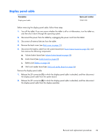
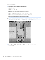
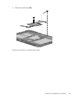
Remove the system board: 1. Disconnect the following cables from the system board: (1) Speaker cables (2) Vibrator module cable (3) Display panel cable from the system board ZIF connector (4) Rear-facing webcamera cable from the system board ZIF connector (5) Front-facing webcamera cable from the system board ZIF connector (6) Wireless antenna cables from the system board terminals NOTE: The wireless antenna cable labeled "1" connects to the "Main" terminal labeled "1". The wireless antenna cable labeled "2" connects to the "Aux" terminal labeled "2". 2. Remove the three Phillips PM2.0×2.5 screws (1) that secure the system board to the display assembly. 42 Chapter 4 Removal and replacement procedures
-
 1
1 -
2
-
3
-
4
-
5
-
6
-
7
-
8
-
9
-
10
-
11
-
12
-
13
-
14
-
15
-
16
-
17
-
18
-
19
-
20
-
21
-
22
-
23
-
24
-
25
-
26
-
27
-
28
-
29
-
30
-
31
-
32
-
33
-
34
-
35
-
36
-
37
-
38
-
39
-
40
-
41
-
42
-
 43
43 -
 44
44 -
 45
45 -
 46
46 -
 47
47 -
 48
48 -
 49
49 -
 50
50 -
 51
51 -
 52
52 -
 53
53 -
54
-
55
-
56
-
57
-
58
-
59
-
60
-
61
 |
 |

Remove the system board:
1.
Disconnect the following cables from the system board:
(1)
Speaker cables
(2)
Vibrator module cable
(3)
Display panel cable from the system board ZIF connector
(4)
Rear-facing webcamera cable from the system board ZIF connector
(5)
Front-facing webcamera cable from the system board ZIF connector
(6)
Wireless antenna cables from the system board terminals
NOTE:
The wireless antenna cable labeled “1” connects to the “Main” terminal labeled “1”.
The wireless antenna cable labeled “2” connects to the “Aux” terminal labeled “2”.
2.
Remove the three Phillips PM2.0×2.5 screws
(1)
that secure the system board to the
display assembly.
42
Chapter 4
Removal and replacement procedures