HP Pavilion 13-b200 Pavilion 13 Notebook PC - Page 57
Release the shielding tape, that secures the WLAN antenna cable to the display back cover.
 |
View all HP Pavilion 13-b200 manuals
Add to My Manuals
Save this manual to your list of manuals |
Page 57 highlights
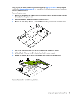
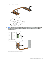
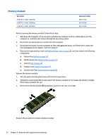
f. Remove the display panel cable (6). The display panel cable is available using spare part number 768027-001, and includes the webcam/microphone module cable. 12. If it is necessary to replace the WLAN antenna cable and transceiver: a. Detach the WLAN antenna transceiver (1) from the display back cover. (The WLAN antenna transceiver are attached to the display back cover with double-sided adhesive.) b. Release the shielding tape (2) that secures the WLAN antenna cable to the display back cover. c. Release the WLAN antenna cable from the retention clips (3) and channel built into the top edge and right side of the display back cover. d. Remove the WLAN antenna cable and transceiver (4). The WLAN antenna cable and transceiver are included in the Antenna Kit, spare part number 768034-001. Reverse this procedure to reassemble and install the display assembly. Component replacement procedures 47
-
 1
1 -
2
-
3
-
4
-
5
-
6
-
7
-
8
-
9
-
10
-
11
-
12
-
13
-
14
-
15
-
16
-
17
-
18
-
19
-
20
-
21
-
22
-
23
-
24
-
25
-
26
-
27
-
28
-
29
-
30
-
31
-
32
-
33
-
34
-
35
-
36
-
37
-
38
-
39
-
40
-
41
-
42
-
43
-
44
-
45
-
46
-
47
-
48
-
49
-
50
-
51
-
 52
52 -
 53
53 -
 54
54 -
 55
55 -
 56
56 -
 57
57 -
 58
58 -
 59
59 -
 60
60 -
 61
61 -
 62
62 -
63
-
64
-
65
-
66
-
67
-
68
-
69
-
70
-
71
-
72
-
73
-
74
-
75
-
76
-
77
-
78
-
79
-
80
-
81
-
82
-
83
-
84
-
85
-
86
-
87
 |
 |
